
|
|
Disassembly & Assembly of heads.
Pistons & rings, Cylinders. Cylinder hold-down studs.
Damaged cylinder stud threads at the case.
Helicoils & Timeserts.
Intake Stub Spigots.
Break-in procedures.
https://bmwmotorcycletech.info/break-in.htm
Article 60, section 1
If you are installing a camshaft and/or followers, read
https://bmwmotorcycletech.info/cams.htm regarding assembly pre-lubrication.
REFER TO MY CYLINDERS article! Lots of information, including about piston rings, etc.
REFER TO MY PISTONS article too!
Working on a /5, with original valve gear? STOP!...DO NOT disassemble the heads and just toss the shafts and rockers into a box! DO NOT mix up the rockers and shafts! See my head assembly article: specifically the section on the /5 valve gear!
You may think that pulling off a jug (cylinder) is major surgery & frightening to contemplate. Once you do it, perhaps at a TechDay, you will no longer have so much apprehension about doing it yourself.
Since this question has come up every year it seems, I will cover it first:
Yes, it is possible to remove a head, perhaps for a simple de-coking (and not pushrod tube seals), & not have to do any work at the cylinder bottom (no O-rings, no sealants). In order to do this, you must very securely wrap bungees ...or via some other means, such as spacers and hardware, to hold things together. Bungees around the cylinder fins, across the motor, & all-around the motor. Or some such. You must keep the cylinders from moving off the base area in the slightest. This method has been done when the only need was work on the heads & was being done 'in the field', such as at a Rally, or a TechDay, & no O-rings and no piston ring compressor were on hand, etc. In order to do this, the bungees must be super-tight & evenly surrounding the cylinder, fore & aft. I recommend you NOT try this ....unless you are most careful. Chances are high that you will not be able to be careful-enough & your cylinders will then leak oil at the base. The airheads list archives have an article or two on doing this job in another way, besides bungees.
Never reuse a head gasket unless the repair is an emergency situation. While it is possible to leave the two head-to-barrel nuts in place (the ones located at 12:00 and 6:00), & to reuse the gasket by never separating the head from the barrel, this is a poor idea. It MIGHT result in distortion of the assembly. I have NOT seen that distortion, if the assembly is done fairly quickly, within minutes. Pure speculation anyway. These 2 head nuts (located at 12:00 & 6:00) are supposed to be the first to be loosened, the last to be tightened (in the usual cross-staging).
In-depth information on the cylinder base shims: https://bmwmotorcycletech.info/cylinders.htmSandblasting, or other media blasting:
I don't like the finish that soda blasting leaves & soda must be 100.00% removed, or it starts its own chemical reactions. Walnut shells are OK. Carbon Dioxide (CO2) is OK. Sand & glass bead blasting are NOT OK (it leaves hard particles imbedded in the aluminum, which can come out & raise hell with the engine innards!) ...with possibly an exception ....the form of blasting called wet blasting or slurry blasting, is often OK to excellent, and leaves a lovely finish. Vapor blasting is relatively safe, even with its use of ultra-fine abrasive particles, if done correctly, and cleaned up correctly. HOWEVER, the labor to clean the surfaces, threads, etc., is HIGH with VaporBlasting. Be very cautious!
It is NOT necessary to remove the piston from the cylinder when just replacing push rod tube seals. It might be a good idea, for such as to remove the rings to check end gaps, etc. You do NOT absolutely have to have a ring compressor! There is an inside taper at the bottom of BMW cylinders, thus you have a built-in ring compressor, in case you do decide to remove the piston from the cylinder ...for such as measuring ring wear, cylinder taper, whatever!! You need to be careful. If you are intending to do a piston removal and a thorough de-carbonizing of the piston and rings area, or, otherwise want to ...then it is fine to use a ring compressor during reassembly. Although de-carbonizing the top of the piston can be done without removing the piston/rings assembly, this is not a good idea, and it is vastly better to do de-carbonizing with the piston out. A thorough job may involve soaking & brushing, over days, of the combustion chamber, piston, and the piston, possibly with the rings removed (I rotate them over the time period). It can also involve an overnight job with 50-50 mixture of such as Simple Green & water; or, a week-long period, soaking in such as the gentler Gunk Hydroseal. If you remove the rings, pay attention to the top/bottom orientation of the rings, a chamfer usually is towards the engine. DO make note of from which groove the rings came and orientation top/bottom, and where gaps were, & don't break them, they are VERY brittle. If you do remove the pistons from the cylinders, it is safest to remove them from the cylinder bottom. When doing a de-carbonizing job, you must clean & clean, & clean again & again, to be sure there are no carbon particles when you are done, in such as ring grooves. For a more complete discussion of cleaners/solvents/etc: https://bmwmotorcycletech.info/chemicalsetc.htm
Avoid allowing the piston rod to fall against the engine cylinder opening ....doing so will create nicks at the engine case ....and the nicks WILL prevent the cylinder from properly sealing. If you nick the case, dress that nick out! I use a rag to gently place the rod on.
Head gaskets fit properly only one way. Be sure the pushrod holes are not the slightest amount blocked. Do not use sealants at the head gasket, nor, usually, at the valve cover gaskets. For the valve cover gasket, use of a NON-permanent, NON-hardening sealant, to get you by ...before fixing any warping that caused the leaks ...is OK. There are aftermarket thick soft silicone cover gaskets available; you cannot take up much pressure on the cover nuts, be sure that the nuts do not loosen; if worried, use a SMALL droplet of blue Loctite. I don't use soft silicone gaskets.
Once in awhile a question comes up about such as the R90/6 & R90S, about a roll-pin, & that these used different head gaskets. That is true, but the old-style gaskets are not available. Remove the roll pin & use the later gasket. For the nerdy (??), the R90/6 changed to no roll pin at serial 4961244; & the R90S at serial 4980480. The cylinder head was modified to eliminate that roll-pin sleeve, & the associated gasket hole was made smaller. You CAN use the later gasket with the earlier head AND keep the roll pin, if you really want to. Regarding the larger hole: The later gasket can be modified to 14-1/2 mm hole, original was 10-1/2 to 11 mm.
BMW's own valve cover gaskets can often be reused almost forever. I use petroleum oil on the head side of the valve cover gaskets ON PURPOSE, which eventually carbonizes & acts like a high temperature mild glue. You can use a mild sealant, such as NON-permanent Form-a-Gasket, VERY thinly. Do NOT get oil or sealant on the outer surface of the gasket ... nor the associated cover surface. The purpose of smearing a bit of oil or the mild adhesive/sealant with your fingertip onto the HEAD side of the valve cover gasket is so it will tend to, eventually, stick to the head, & be much less likely to tear as you remove the cover for such as valve adjustments. When removing the valve cover, remove slowly and carefully, and if the gasket begins to come away on an angle, instead of remaining in contact with the head, simply use a tool to push it back to the head, carefully. Carefully done, the gasket may last the bike's lifetime.
A longer, & now standard, 70 mm length central stud for the valve cover is available. Always install these with Loctite red (a strong type) at the head end. This longer stud is 07-12-9-908-142; the original was -145 (8 mm x 65 mm). I recommend the longer one be installed if your stud does not engage all of the head threads. Have at least 4 threads on the acorn nut engaged, AFTER the thick flat washer is installed.
The /5 models had valve gear that could be moved-around to quite an extent. Adjustments are elsewhere's on this site.
A question comes up now & then, whether or not an O-ring is used under the /5 rocker blocks. The O-ring was 11 12 1 255 167 which became the later number 11 11 1 460 470, 15 x 2.5 mm. If you need these, I suggest you get slightly bigger ones from the aftermarket (15 x 3 mm perhaps).NOTE: I received a message from someone in Germany who said that an aftermarket 14 x 3 O-ring also prevents any leaks.
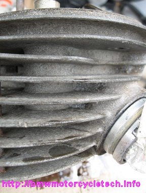
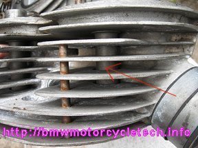
Below are two photos that will identify which head requires the O-rings.
Below head does not need the O-rings as the casting surrounds the tube.
Below head does need the O-rings, the large tube appears with no surrounding casting. NOTE THE RED ARROW!
Disassembly:
For information on the cylinder base shims, see Section 60-3: https://bmwmotorcycletech.info/cylinders.htm
First set engine rotation so the OT mark on the flywheel/clutch carrier is showing in the timing hole. That means pistons are fully outwards. Then remove the valve covers slowly and carefully so as to not tear the gasket, and remove the spark plugs. Loosen the rocker arms valve clearance adjusters almost entirely, so the rocker is very free to move over a VERY wide arc. Check the rocker bearings, whether the old /5 pressed sleeve type or the later needle bearing type, by twisting the rocker sideways. Inspect the ends of the rocker arms, particularly the lower side, where the needle bearings (not /5) are pressed-in ...if bad, replace the bearings. /5 models use bushes, not needle bearings, unless upgraded previously. The Section 60-6 article on this website has information on the specifics of how to swap-around the original type of /5 rockers themselves to extend their life (without having to replace the bushings):
https://bmwmotorcycletech.info/headassy.htm.
There is a LOT more information on these rockers, bushes ....and for later valve gear, in that linked article! Good idea to read it completely!
Undo the 6 head nuts, in stages, evenly, & remove the valve gear. Do NOT disassemble the valve gear (keep the shafts, rockers, blocks, all together as units), nor mix the parts from one cylinder to the other, nor mix up exhaust/intake rocker assembly parts. Do NOT pull the rocker assemblies apart as needles may fall out (needles were used after the /5). If you do, & you have the needle roller type, the correct number of needles is one less than what will JUST not quite fit. Again, leave things together, remove the rocker assembly as just that, an assembly. It is a good idea to inspect the needle bearing rockers for any problems with the needle cage ends. Look particularly at the rolled-over ends of the needle bearing holders. Don't pull the shafts unnecessarily out of the rockers. There are tiny needles in the later models, & some can move into the center area. Those can be a minor PIA to put back in place as noted.
NOTE: The punch-prick OFFSET marked & angularly drilled shafts CAN be rotated end for end for additional life, with the mark now facing inwards. But, check the drilling in the shaft first ...be sure yours are such that oiling is maintained. The rocker shaft will likely have a round darkened area on one end, or you will seen a punch prick mark. You have probably been told that the darkened area MUST be on top, the punch mark, when present, must be outwards, when reassembled. Actually, having the punch mark outward is not absolutely necessary, with the angularly drilled shafts (NOT all WERE). Best for you to do it this way: top, outwards. This avoids me having to make a very lengthy technical explanation with graphics & have you check your particular shafts for proper drilling.
Remove the cylinder head & remove the pushrods.
Pull the cylinder outward just enough so that the rear piston pin clip is just fully showing. By not pulling the cylinder off more, which means not removing the piston further, you keep the piston rings inside the cylinder. IF you are doing a thorough de-coking, or measuring taper or ring gaps, then remove the cylinder off the piston, but in any case don't let the rod fall; and for extra protection from that, do stuff a rag under the rod ...as you do NOT want the rod to nick the case!; that will make for oil leaks, unless you carefully dress the nicks out. If you decide to remove a piston clip & remove the piston pin (you may have to heat the piston to remove the piston pin), be careful with the pin clip groove. Vorn marking & arrow on the top of the piston means that the arrow points forward on re-assembly. That is important; and, note that, if rarely, a piston is not marked correctly. Do check...more a bit later on that!
Don't be ham-fisted about the piston pin clip. Once one is removed you can push the pin oppositely (heat piston if needed to remove the pin) & carefully place the rod downward on the rag; pull the cylinder off, piston & rings still in the cylinder. No nicks are allowable from the rod onto the cylinder base area! Do not mess up the piston pin area. I most often replace the clips, which is the best policy. When replacing wrist pin circlips, they have a sharp side & a rounded side; the ROUNDED side goes INWARDS, & orient the gap towards the engine case. Be SURE the piston pin clip is 100% properly seated, ...try rotating it to be extra sure.
Note:
For 1978, BMW changed the piston pin clip to the better EXternal type on the R80 models, and phased that in on the R100 models.
Keep in mind that any nicks on the cylinder base & engine pad base will cause oil leaks; so if you have any nicks, dress them out!
If the piston pin seems too tight to push, push the pin a tiny amount, if it will ...it likely still won't move. Look for metal fouling at the clip area ...the tiniest amount is too much & will keep the pin from being pushable. Still too tight? Try using a hair dryer or? to heat the piston. Heating the piston expands the aluminum far faster than the steel pin. PROBLEMS?....see the next several paragraphs.
Only in a rare case (with a heated piston) have I had to use a simple home-made device to remove the pin, the so-called 'draw-bar' method. A draw bar can be simple. DO get rid of proud metal at the clip place, and DO try heating the piston pin area quite hot first. For a drawbar, if such is necessary, you will need a piece of all-thread from the hardware store (& get 2 nuts), not too large, or it won't fit through the pin. Use some sockets from your socket set, or a big selection of washers & nuts, & draw the piston pin out. I've even used sockets or other proper diameter spacers and very large C clamps. Below are details & an example of how you might do this. CAUTION! ....You must not put pressure on a piston clip! Huge amounts of pressure are not need, and are NOT TO BE DONE in this pin removal procedure! The clip is often called a KEEPER. This procedure works well for piston pins that have the center hole totally available to put a piece of all-thread through it. There ARE types of piston pin keepers that don't allow this unless BOTH are removed.
Read this procedure THROUGH ...KNOW what you are going to do!
1. Cut the all-thread to reasonable length with the nut ALREADY on the end to be cut, with the threaded area to be cut off NOT having the nut on it. This means you must put the nut on first, with some threads showing at the end. I clamp the nut lightly in my bench vise, then I cut off any unneeded threaded material. Clean up the end with a file, wire wheel, whatever, & then unscrew the nut, removing it completely, to finish re-forming the cut threads . You can now do a final cleaning of the first thread. The all-thread needs to be long enough to enable nuts, washers, sockets, whatever, as spacers on it. BETTER way long than too short! THEN put the piece of all-thread through the hollow piston pin. At the forward end (assuming pin will be pushed rearwards in this procedure), put a washer or socket, sized such that it fits the piston pin end, but does NOT pull into the insides of the pin, NOR put pressure on the piston, nor clip, if it is there. In other words, it is sized just a bit less than the pin diameter. Add a nut. Check & recheck the size of your items being used as a spacer/mandrel. YOU DO NOT WANT TO DAMAGE a piston pin bore or clip, or pin.
2. At the pin area, put a large socket that is much larger on its INside than the piston pin; add a washer if needed for the nut to bear on. Put on a nut. Tighten this rear nut. The tool will draw the pin to the rear. HAVE THE PISTON HOT. WATCH what you are doing ...you DO NOT want to injure the piston pin bore area. You may have to put a large socket or piece of pipe, etc., that fits & clears, over the pin, & repeat the pulling, over & over. Note that you can improvise, a lot, on this technique. Done properly, you will NOT scratch the piston bore where the pin fits the piston. The pin is a much easier fit in the rod, & you need only remove the pin enough to free it from the rod (don't let the rod fall).
3. Some pins fit tightly, & heat ...and more rarely heat & the drawbar method ...are needed. Do NOT go to the effort of the drawbar method if a pin removes without a drawbar. If the pin does not move, then heating is the first thing to try. Simple heating of the piston with such as a hair drier works may allow you to push the pin out with your thumb. Pins and piston bores are a VERY carefully machined fit. Be really careful not to damage the piston pin keeper area. If you put the slightest nick in the area, you will have to remove it with a sharp knife or some other method, or the pin will NOT remove easily, nor will it go back in place easy, later.
4. With the pin is out of the piston & rod (DO NOT let the rod fall and nick the engine case!!); the rod gently placed on a rag on the engine casting hole entrance; you can pull off the cylinder, with the piston & its rings still in the cylinder .....you need to remove the piston, of course, if doing a ring job, honing, ...etc.
Assembly and break-in:
For information on the cylinder base shims, see the CYLINDERS Section 60-3:
https://bmwmotorcycletech.info/cylinders.htm
https://bmwmotorcycletech.info/pistons.htm has the ORIENTATION of the piston rings, and lots more.
see also: https://bmwmotorcycletech.info/cylinders.htm
Pistons occasionally are manufactured with the VORN marking and arrow stamped wrongly ...that is, in the 180� reversed position! Be sure you have the piston installed in the correct direction! Pistons have the larger cutout relief for the intake valve, and this larger cutout always faces the rear on the Airheads. Piston pins are also not dead centered in many types of pistons ....that isn't easy for you to measure ....so is just a somewhat nerdy mention here.
I suggest that you do not use the BMW owner's booklet method of break-in; IMO, it is for an engine already briefly run at the factory.
OIL:
You may be 'breaking in' a ring job or pistons, rings, cylinders, or bore job, or some combination. BMW, long ago, used a special 20W20 oil delivered with new bikes; I do not know what they use presently. There is no absolute need for special oils if you are breaking-in new rings; but there are some strong suggestions by me. I suggest a SG type oil, non-synthetic; a 10W40 for break-in; although a semi-synthetic is OK, as is 15W50 or 20W50. If you plan to use a straight weight oil, such as a SAE30, that can work OK, but avoid cold weather break-in starting. If you replaced cam and/or followers, then be sure the break-in oil contains a decent amount of ZDDP. A NON-synthetic (non-part-synthetic too) MAY WELL allow faster break-in. BMW (me too) says a full break-in may take 6000 miles, for minimal oil consumption. DO NOT USE A FULL SYNTHETIC OIL FOR INITIAL BREAK-IN! See next two paragraphs. I highly suggest you break-in the top end of the engine using a decent motorcycle oil, my preference being Golden Spectro 4 which is a part-synthetic; but I approve of NON-part-synthetic oil too. Spectro makes such an oil & it works delightfully for break-in. DO NOT USE A FULL SYNTHETIC OIL.
I strongly suggest you do NOT flood the rings, cylinders, nor pistons with oil during assembly. Use at most a dozen drops of the engine oil on your hands, & then wipe your hands onto the piston skirts & rings. Wipe the cylinder walls too, but only quite faintly. Excessive oil causes carboning-up, particularly on new rings, & INHIBITS BREAK-IN! I like the faintest oil film ...REALLY THIN!
I recommend that the engine NOT be babied. This is especially important at high altitudes where cylinder pressures, even with full throttle, are much lower. Lower cylinder pressures mean that the rings are not being forced against the cylinder walls with as much pressure. The problem that arises with too gentle use of the throttle is various forms of glazing, and failure to seat the rings and cylinder walls properly, the result is excessive blowby and oil usage.
Install a new oil filter, using the starter motor (no fuel in carbs so engine will not start) to fill the oil canister area (oil light goes out). Turn on the fuel petcock(s) and start the engine using a minimal amount of 'choke', and within seconds move the rpm to about 3000 & hold it there for maybe 15 seconds, then move it upwards to maybe 3500 or even 4000 ...for perhaps a minute. Turn off the engine after that minute & check for oil leaks.
Immediately put on your riding gear. Restart the engine; and, with no waiting, go for a ride. DO NOT baby the engine much ...use a fair amount of throttle but NOT near maximum, ....although at high altitudes I WOULD USE MAXIMUM for a FEW seconds at a time ....BUT!! ....even with maximum throttle (or not) DO NOT use over 4500 rpm for the first dozen or so miles. Keep the engine around 3000-4500, as best you can, backing off the throttle FULLY every few blocks (or, every half-mile), then increasing throttle so the rpm is back in that 3000-4500 range. Backing off the throttle fully is important, to 'suck' oil up into those areas needing it. Might be a good idea for you to re-read and fully memorize this paragraph.
As you get ~ 5 to 10 miles on the engine, you can begin to use slightly longer stretches before backing off the throttle. The idea is for oil to be sucked into the rings & valve guide areas when the throttle is snapped off. The snapping-off works best if you can do it for at least 3 to 5 seconds. It is OK to use a fair amount of throttle, but usually not wide-open throttle (I DO use full throttle for a few seconds, often, if at high altitude, that is, over 5000 feet), and do not use extremely high rpm, absolutely NOT even close to redline! After a dozen+ miles, you can move slightly higher in rpm. Don't idle the engine for long periods of time. NO REDLINE RPM, keep WELL below any yellow area too! After a fair amount of miles, stop, turn off the engine, & again check for oil leaks. If no leaks, continue your ride. As initial break-in continues, you can use higher & higher rpm for short bursts. I suggest staying under 5500 for the first 100 miles, and this applies to ALL sizes of Airheads engines.
I suggest continuing the initial break-in somewhat as in the Rider's Manual ...modest rpm, vary the rpm, vary the throttle, etc., & avoid very high rpm. You COULD go 600 miles before an oil change, due to the oil/filter system. For the very best for your engine, I suggest after 100 miles or so you change the oil to a quality 20W50 MOTORCYCLE oil but do NOT use a FULL synthetic (should you plan to, eventually) until the engine is fully broken-in, which can often take several thousand miles. Full synthetics are not needed on an Airhead, but can be used if you so prefer, AFTER a very full break-in, which will be thousands of miles.
Change the filter; hang it by a piece of coat-hangar wire, overnight, and the next day inspect the pleating; that is, disassemble the filter by prying the metal ends off the filter, then knife-slit the outer wrap, then unroll & inspect all pleats on both sides. It's a good time to check the valve clearances, engine cool. Check the valves again after 600 more miles, particularly important if the valve clearances are changing a fair amount. You want to be sure the valves are stable over time. Once the valves are stable, every 5000 miles is OK. I keep written records of valve clearances at every check, and certainly before the head bolts (nuts) are checked for torque. I suggest you do not torque the 6 nuts at every valve adjustment/check. Initially upon assembly, then at maybe 100, 600, 5000, and then very seldom. The rockers end play adjustment does require loosening the 2 rocker nuts some (do ONE rocker at a time), so that is a good time to finish the job by tightening all 6 nuts per cylinder. Use a torque wrench.
Assembly and break-in; ....in more depth:
The so-called dry cylinder break-in information was posted quite a few times to the Airheads LIST by Tom Cutter. My method is similar (and is shown above). I am using Tom's posting as a basis for what follows. I have edited it for syntax & clarity. Still, what follows is MY method, COMBINED with Tom's method, said somewhat differently than previously. We do NOT differ much between us! FURTHER, our procedure is nearly the same as BMW posted (via Butler and Smith) decades ago.
The "Dry cylinder" method does not mean 'don't oil anything'. It means don't flood everything with oil on assembly and do not use special assembly lubes for the cylinders and pistons and rings. I use such extreme pressure lubricants only for assembling connecting rod bearings, mains bearings, camshafts, & cam followers.
Honing: Be careful that you understand what honing means. Basically, honing puts a desired surface finish onto the cylinder. During the process, the rotary hone and its RPM and its vertical speed as it goes up and down through the cylinder, creates a cross-hatch type of visible finish. This is the basic process, for iron or steel cylinders, whether or not the cylinder is later 'plated' with something like Nikasil/Galnikal. The cross-hatch pattern angle has been debated, but done properly, the engine will break-in nicely & also use less oil, and the cylinder will last longer, ETC. The crosshatch pattern has quite an effect on ring rotation, and some other things.
Honing seems to often mean different things to different folks, & is not the same thing for honing a fresh bore job on an older iron cylinder, as what it means for a Nikasil or Galnikal cylinder which are not truly being honed, that was probably done before the "plating" or by a plasma coating. When the cylinder is being prepared for installation into your motorcycle, you must thoroughly clean & wash the cylinders & pistons, rings, etc. with a solvent. Tom uses Safety-Kleen solvent, I use kerosene or paint thinner, ETC.. I finish with hot soapy-detergent-water, then follow that with a hot water rinse.
I do NOT "hone" Nikasil or Galnikal cylinders. Tom feels a simple "ball-hone" "could be" briefly used (I agree). I use 3M type plastic scouring pads with plenty of soap & water to clean those particular bores. Nikasil shouldn't be considered for conventional abrasive honing. The factory Nikasil honing marks are usually quite visible, and last a tremendously long time/mileage.Blow dry with compressed air & leave in the sun to dry. If you don't have compressed air, use clean, soft and absorbent cotton to dry the cylinder bores.
On the iron cylinders (Airheads, pre-Nikasil/Galnikal), I generally let the cylinders, after the soap, water & sort-of drying, to sit in my garage or storage shed, to actually get a very faint patina of rust, which may or may not be noticeable. Usually overnight is enough. But, I may let it go longer. THEN I use a VERY SLIGHTLY oily rag ...or my SLIGHTLY oiled hands ...in the next day or two or three ....to wipe the cylinder walls. This prevents more surface rust, & makes everything slide together well, & leaves a TRULY FAINT abrasive-lubrication layer. You want the surface just barely noticeable as faintly having a sheen of oil (at most).
Nikasil or Galnikal cylinders do not rust, but the FAINT amount of oil from one's hands, as earlier described, fills in some pores & irregularities.
Summing-up: I use a faint amount of oil on both the iron & Nikasil or Galnikal cylinders, but I never have a wet squirted-on oiled cylinder look.
Assemble the rings onto the pistons if they are not already so. I prefer to do my faint oiling to the cylinder walls and the pistons with the rings on the pistons. I caution that rings are very brittle and you must install them correctly and not upside down, & the gaps are to be at 120� & the gaps at the O'clock I specify below. I have my methods of installing the rings, but you can use an old thin feeler gauge to help you, using it as a sliding surface. Here is the proper orientation of the ring end gaps, based on the common analog clock, as you face that side of the engine:
LEFT SIDE:
Outer, compression ring: 4:30
2nd ring: 10:30
Innermost (oil ring): 1:30
RIGHT SIDE:
Outer, compression ring: 7:30
2nd ring: 1:30
Innermost (oil ring): 10:30
YOU MAY WANT TO READ THIS ENTIRE ARTICLE:
https://bmwmotorcycletech.info/pistons.htm
NEXT: Install the pistons into the bottom of the cylinders until just the skirts & wristpin hole is showing. VORN and the arrow on the top of the piston faces FORWARD! SOME FEW pistons were mismarked. The EXHAUST cutout is the smaller one. Then slide the cylinder (if the cylinder uses the very large O-ring at the cylinder bottom install it first) onto the studs; line up the rod wristpin holes. Put a few drops of oil (or, assembly lube) on your fingers & oil the wristpin & bores, then install the pin & clip. BE SURE that if your clip is sharp on one side & not the other, that it is installed correctly as previously outlined in this article! Be sure it is FULLY installed! If the pin is tight, heat the piston with a heat gun. If the pin is still tight, clean the burrs in the pin bore. Once the piston pin is installed & its clip is secure (put a rag in the crankcase hole to keep the pin from flying in there) you are ready to finish installing the cylinder. Be very careful about installing the pistons with rings....it is altogether too easy to fracture a ring. You can install the piston with rings from the top of the cylinder (outer, head end of the cylinder) if you are worried about installing the piston from the bottom.
Apply a very thin coating of your sealant of choice (see my chemicals, etc. article) onto the cylinder base sealing surface & both sides of the shim/gasket/compression-plate (if the bike uses gaskets or compression plates ...information on these is found, in depth, in: https://bmwmotorcycletech.info/cylinders.htm as well as onto the crankcase surface. NOTE that the sealant must be VERY thinly applied. Finger-tip applicator is best. If you use a brush do NOT allow ANY bristles to remain ...none!! Be sure you know exactly where & how to install the sealant. It is placed very carefully on the cylinder base and especially carefully on the engine case, around the OUTSIDE of the top two studs. The top two studs are critical where they meet the engine case. The ONLY oiling for the rockers, and other parts of the top end, is via the oil that comes to the head along the studs! You do not want the oil ports gooped! These are tiny ports where the top two studs of each cylinder fit into the engine case!
IF you use Hylomar, & with some others, warm the tube of the stuff somewhat so it's brushable (or finger-tip-able). The film must be very thin & relatively even. There must not be ANY brush bristles left on the surface. There have been a few problems using Hylomar, the sealing fails, usually after some longish period of time, possibly due to imperfect application, not letting the Hylomar sit for awhile after application, BEFORE assembly. Hylomar is a bit safer than many other sealants, if a tiny wee bit gets into the oiling system from a slight over-exuberant amount at the top studs. Please refer to the following article for recommendations on cylinder base sealants & applying them:
https://bmwmotorcycletech.info/chemicalsetc.htm
Apply two or three drops of regular non-synthetic (part-synthetic is OK) motor oil to each side of the piston skirt, top and bottom, and the cylinder walls. I put these few drops of oil on my otherwise clean hands, rub my hands together, and then use what is on my hands to very faintly coat the piston and cylinder walls. I do NOT use 'assembly lubes' here.
Lightly oil the pushrod tube rubbers on their outsides so they can slide easier into position. I use a faint smear of silicone grease on the inside of the pushrod tube rubbers, where the pushrod tube fits. Silicone grease is often called, at autoparts stores, silicone dielectric grease, or similar.
If your cylinder (1979+, usually) uses the very large O-ring at the base, now, not earlier, is the time to oil it, using your finger, using engine oil. I also NOW oil the small O-rings at the top two studs at the engine case. Within a minute or three, push the cylinder fully home. Don't extend this time to hours, as the O-rings might expand. Do not delay, go to the next step:
Next, install the head gasket so the writing faces you, (double check that there is no gasket covering any portion of the head pushrod tube holes ...if there is, the gasket is reversed, no matter the writing faces!), & install the heads & well-oiled rocker arm bushes/bearings, without delay. I do the head tightening with a bit of bias to the bottom two nuts of the rocker assemblies; as, otherwise, the push rod rubbers act a bit like a canting (angular), spring.
Torque the the cylinder head in a Cross Pattern, but in a progressive 3-step torque sequence, to 25.0 foot pounds of torque. BMW never specified in any detail if the 4 rocker nuts & associated studs are to have oiled threads, or not, when assembling & tightening them, or, really, all 6 nuts per cylinder head. I, however, will tell you. You SHOULD oil the 4 rocker arm stud threads (on each cylinder head) & also oil the nuts threads ....before screwing on the nut. If they ever squeak during tightening or loosening, remove, oil, re-torque. If you oil those two nuts, do it skimpily. It is not absolutely necessary to have any oil on the threads on the two head nuts, located at 12:00 and 6:00, although a trace of oil film is fine on them ...and that IS what I DO ...either a scant ONE drop on the stud threads before I put the nuts on, or, I simply have a slight bit of oil in the solvent when I am cleaning the threads.
Tighten the 6 nuts holding the head & cylinder evenly & in a cross pattern. DO ONLY ON A COOL ENGINE. Once the cylinder is pretty well up to the engine then be sure to 'stage' the torque settings, perhaps first at a few ftlbs, then 11 ftlbs and then 18 ftlbs. Do that in the same cross pattern. Do NOT go directly to the final 25 ftlbs value. The final torque setting varies officially by year and cylinder type. BUT!.... I strongly suggest you use 26.0 ftlbs as an ABSOLUTE MAXIMUM for ALL BMW airheads, and set your torque wrench for 25 ftlbs, which is my personal torque value, ALL Airheads. I strongly suggest you disregard any advice in literature that, especially on the old iron sleeve cylinders, says to use 29-31 ftlbs. DO NOT EXCEED an absolute maximum of a true 26. BE SURE your torque wrench is accurate.
DO NOT USE a torque wrench of quite high maximum available setting. Use of such as a 150 ftlb maximum setting torque wrench will probably result in poor accuracy at the much lower settings. A 75 ftlb maximum torque wrench is what you probably should be using. Besides the inaccuracy at low settings for high limits torque wrenches, there is another problem with them. Many torque wrenches have an extremely soft 'feel' or 'click' at low settings. I have seen folks put a LOT of torque on those six head nuts ...beyond the 26 ftlb max ...simply because they did not know what to feel for. If you do not know how your torque wrench feels, test it on something other than your top end nuts! Put the square drive into your bench vise, and feel and listen for the click.
I absolutely will NOT use a beam type torque wrench for this job, unless it is the industrial type, that has a GAUGE on it.
Rockers (rocker arms):
A good reference for the rockers, which has some photos and discussion, is: http://largiader.com/tech/rockers. That is Anton Largiader's site, and he has photos in that article of what the various years of rocker items look like, etc. BTW ...if my memory is OK here, the early rocker arms were ~56 mm wide; later ones used from 1985, were ~51 mm. This allows for the shims used on the 1985+ rocker arms. If I get a chance, I will measure them and post the exact measurements here. Not really important as wrong ones absolutely will not fit.
If the adjustment of the cup-bolt (to set valve clearance) is not adequate after head has been milled, see the information in: https://bmwmotorcycletech.info/valves.htm
You can now (or later) adjust the rocker arms for end clearance, and then (or, do later) adjust valves for clearance. Valves must be adjusted with a cool engine with the particular cylinder at the OT mark ON THAT PARTICULAR CYLINDER'S COMPRESSION STROKE. When doing end play adjustment, the rockers must be free; I suggest they be tested that they WILL rotate fully. Have the push rod adjustors backed WAY WAY off for that. Proper end play is such that up & down pushing on the rocker will "just" show the oil film to move at where the rocker meets the rocker mounts. I personally do the first rocker end play & valves clearances adjustments all immediately after the cylinders & heads are installed. I do it during the torquing of the rocker nuts.
In ~600 miles do another valve clearance check; re-check the 6 nuts (per head) torque at that time; check the end play too, end play must be checked when OT on the flywheel is shown in the timing window, on compression stroke, for the cylinder you are checking. In that position, you should have the proper valve tip clearance. Keep records on clearances as found ....so you have trend information! I always find this OT/TDC compression stroke point on the LEFT cylinder, and then check the LEFT valve clearance. I only have to rotate the engine one full turn to have the RIGHT cylinder at OT/TDC, compression, for that RIGHT cylinder.
Late models (1985+) have clearance specifications, and the rocker end play is set with shims. I still use the oil film check.
Double check that there is a proper level of engine oil!! Folks have done top end work and forgotten to put oil in the engine (assuming they drained it!)!
Prepare your carburetor adjustment tools, for later.
Follow initial startup & initial break-in, as shown in an earlier section of this article. IT IS IMPORTANT THAT THE VERY FIRST STARTUP BE PER MY INSTRUCTIONS! If carburetors were worked on, do a preliminary adjusting the carburetors withOUT starting the engine.
CYLINDER HEAD SPIGOTS:
These are the large round metal intake stubs that fit into the cylinder head, to which fastens the hoses to the carburetors. The stubs are made of steel, threaded at one end to screw into the cylinder head. Occasionally stubs come loose or are leaking. The easy test for that is to spray brake cleaner or other stuff, even gas from a torch, at the junction, at idle rpm, and there must be no rpm/sound change. To be sure it is a loose leaking spigot, and not the hose, spray with a wand carefully. Generally speaking, we 'Wrenches' have advised removing spigots by heating the head fairly hot, which expand much faster, being of aluminum, than the spigot. Re-install the spigots very tightly after coating the threads with Loctite Red. The factory installed them, or was supposed-to, with a green-wicking-Loctite, at a specified torque & head temperature. For reference specifications purposes here, BMW said 240�C (which is 572�F) ...that is REALLY REALLY HOT! (I get nervous about head warping at such temperatures)...... I never heat the heads that hot. The factory also said to use a torque of 12 mkp, which is approx 88 ftlbs and 118 Nm. UNfortunately, the factory, in making up even the factory service manual (all I have looked at), decided mkp and Nm were the same, and said 12 Nm.....and I can guarantee you that 12 Nm is insufficient for these stubs. I've seen errors in other literature too.
I want to make it clear about that temperature. BMW can get away with such a temperature since the heads are not yet finished-off. They are also using a wicking method of Loctite application. You should not. I strongly suggest you do NOT heat the heads that hot! I suggest: Heat head to water sizzle temperature (about 100�C, 212�F) or a bit more. I use an electric hot plate, with a separating piece of aluminum. I suggest that you do not go over 300�F. I clamp the head into my bench vice, using wood in the jaws to not injure the head in any way. Prepare for this ahead of time. Use a common strap wrench or a special adaptor to fit the stub. Use Loctite RED (very strong, and high temperature) on the spigot threads (all of the threads), and install VERY TIGHT! No strap wrench? Make up one from an old leather waist belt. Spigots with carburetor end slots? ...you can use something as a tool ....such as a flat piece of steel. VERY TIGHT! The reason you must tighten so tight is that you are not heating the head to BMW's factory temperature of 240�C, nor are you using a weaker wicking Loctite either, to be correct here.
If the engine is already assembled and you do not want to remove the heads; prepare for all the following ahead of time:
Run the engine until fairly hot, then shut off the engine, quickly undue the carburetor, quickly remove the offending spigot, quickly clean-up the threads if needed .....and immediately apply a high temperature Loctite (standard red stuff is OK).... and reinstall quite tight. You can use a strap wrench, or, fashion something .....get that ready ahead of time. Do not bugger-up the spigot.
Repairing pulled cylinder stud threads:
(If you cannot follow directions, DO NOT do these repairs yourself)
There is additional information, links to videos, etc., in my tools article:
https://bmwmotorcycletech.info/tools.htm
Scan down to item #20.
WARNING! ....never tighten the 4 rocker arm nuts if the engine is warm; or worse, if hot. That can cause pulled-threads.
There are 8 studs that are screwed into the cases, 4 per side, that are used to hold the cylinders and heads to the engine.
Originally, the studs were
11 11 1 257 397 275 mm, 10 x 1.5 mm. These were the standard studs used. From approximately 1977, with the R100 engines (and, specified for later too), there were only 6 of these, used at all positions EXCEPT the RIGHT REAR. For the RIGHT REAR the stud length was increased, and a new number assigned: 11 11 1 265 195, which were the same threads, 10 x 1.5 mm, but the studs were longer, 297 mm. These two longer studs are used at the right cylinder. Restating where used: top and bottom REAR of the RIGHT side of the engine. Specified length of the installed stud has varies with various Experts, Guru's, etc. ALL Cylinder studs are to be installed so they are 9-15/16" to 10" from the engine pad; 10.0" is my goal, but I am fine with such as 9-7/8". Do NOT use Loctite on the threads! The reason for the longer studs has to do with the rear main bearing to strengthen the case against cracking....this was apparently seen on the R100 engines at extremely high power output (VERY high RPM). That's the only information I have for you at this time.
I like Helicoils FAR better than TimeSerts or similar for this application; when you need them. Properly done, the Helicoil has no oil flow problems (oil passageways). If you are repairing a botched-job, you may well require special advice, perhaps on the Airheads LIST. See below for the best tools and repairs, HPD ...and there are others that are good enough.
Done properly, a pulled stud repair can be as strong ....or stronger ....than the original. In most instances, a proper repair is far stronger than the original. Only in the really horribly bad instances have I found it necessary to do welding. One must be careful about the oil galley feeds to the top studs, no matter how repaired.
The best repair is done with special tools & inserts. This is particularly true for the upper front LEFT SIDE thread, which BMW had factory assembly problems with on the later Airheads. I recommend HPD (High Precision Devices) tools. Try: (303) 447-2558. Their toolset is expensive. It may be considerably cheaper to take the bike to someplace that has this particular set of tools. This is NOT a standard Helicoil repair. You could also 'rent' a tool: http://www.northwoodsairheads.com/cyl-stud-jig.php
The above may no longer be renting the jig. You can check with them.
Another source: Willcraft Company, of Boulder, Colorado: https://willcraft.co/products
| This is being placed in a warning box. I cannot over-emphasize that any threaded hole in the engine case that is used for one of the 4 long studs for a cylinder must be repaired properly, should they need repairs. Pulled threads are rather common. BMW themselves installed special length Helicoils on the Airheads motorcycles at certain positions, due to casting problems. If you take your motorcycle to a repair shop, friend, etc., & they plan to drill or tap your case holes by using a hand drill, electric or not, & not use a proper drilling/tapping guide, do not ...NOT!!! ...let them touch your bike! NO MATTER WHAT THEY SAY ABOUT HAVING DONE THIS JOB PREVIOUSLY FOR OTHERS. Failure to heed my advice could result in, worst instance, a scrapped engine block. PLEASE BE CAUTIOUS. Use of correct tools to do the job should be thought of as MANDATORY. ASK your BMW Professional what jig or drill/tapping guides tooling they will use. If leaving your bike/engine for such repairs, ASK to SEE those tools! You want to KNOW they have them AND will USE THEM! You've been warned!
The rest of this section of the article, before getting into the cylinders, O-rings, etc., is devoted to the problems with the case threads. |
BE SURE YOU UNDERSTAND THIS!: ALL oil for the valve guides, rockers, pushrod tips, and some oil for the camshaft, ETC., comes from the high pressure OIL GALLERY (think of a gallery as an internal pipe or cast-in pipe). The gallery is supplied from the oil pump and oil filter. The gallery supplies oil to the "top end" via two very small holes located in the engine case, one each is located at the TWO TOP CYLINDER STUDS AREA of the engine case. To repair pulled threads, where a stud has pulled out of the engine case or is close to it, it MUST be done properly, as there is a lot of torque on those studs when tightening the head nuts. You MUST ensure that the oil passages continue to be functional. Note that the path of the oil to the cylinder head is along the two upper studs themselves! I recommend the OIL passages at the top studs be plugged during any machining work. You could use candle wax ....remove it when done. A typical repair will have you using a special guide to allow precision drilling & tapping threads & installing a special extra-long Helicoil at the top studs area. Rags should be stuffed into the ~4 inch hole where the cylinder fits. Grease the DRILL & same for the TAP, to grab chips during the repair process.
If you are not doing the repair with the HPD tools or a borrowed tool:
The standard fix for pulled threads is to use a Helicoil drill & Helicoil tap & tool that comes in a Helicoil kit. The thread that you are going to make in the case is 12 x 1.5. The Helicoil is then inserted into that 12 x 1.5 thread. The Helicoil has the same pitch (1.5), but after installing it, the result is the stock 10 mm where the stud screws-in.
If the threads are fully pulled-out, you probably won't need to drill the area.
BMW does not use the standard typical 9 coil Helicoil that one finds in stock at your Helicoil dealer. BMW uses a longer Helicoil, it has 12 coils. The BMW part is ...or is supposed to be ...already coated with Loctite. There is no need to get the entire BMW kit. You can order the special long Helicoils from BMW, 11 11 1 338 630. The entire kit is BMW part number 88 88 6 112 730, and it included a Helicoil tap, a tool, and a drift tool. $$$, but perhaps worth it. BMW rightly said that if the threads were totally pulled out, one need not drill (a guide IS needed if you drill), and one could proceed directly to the tapping for the Helicoil. Tapping MUST be done with the special Helicoil manufactured tap, & a tapping guide. I suggest, MOST emphatically! ...that this job never be done (drilling or tapping), without a truly proper GUIDE! Drilling & tapping is critical! If you plan to have this repair done by someone that tells you that he can do it with an electric drill, by hand, without a guide piece ...RUN LIKE HELL! EVEN A SLIGHT ANGLE will be reflected in a large amount of stud offset at the head ....and bad things can happen over time. There can also be serious problems with the oil gallery holes.
You can also obtain longer Helicoils from Helicoil dealers. Use of the long Helicoil ensures a very strong repair. Use the regular Helicoil tap tool, etc. A drilling and/or tapping GUIDE is absolutely necessary! ....to ensure a dead straight & square repair. Information on some of this is in the 12/92 service microfiche, page 3, area I23 and J23. The SI was 11-047-91 (2461), and covers ALL R models. The SI calls out installing the Helicoil to a depth such that it is 2 mm below the surface. NOTE, that BMW had a note on this SI....stating, my words here, that the correct specification for torque, using a known calibrated torque wrench, was 25 +- 2 foot pounds, and that "this did not mean torque to 27". BMW wants Loctite on its inserts, and supplies their 12 coil insert with such a coating, per their books. I have literature from the Helicoil company that says NOT to use Loctite on their inserts, as it can cause them to slip (rotate). I disregard that literature as I think BMW is correct in this instance. I install Helicoils with Loctite RED, and after a full cure (a few days), I thoroughly clean any excess Loctite using Q-tips and acetone ...I don't want any excess or uncured Loctite to be in the stud threads ....just the engine case threads interface to the Helicoil itself. ALLOW TIME FOR A FULL LOCTITE CURE!
In the top oil galley holes, they are at 12:00, be exceptionally careful about the oil function ....do not block the galley hole, and ensure that the Helicoil does not interfere, ETC. Remember, there is a rubber O-ring used on most models there too. Think about that O-ring ...it seals for oil leaks & must still allow for oil to pass to the top end. A very close "thinking man's look-see" is needed to understand how the oil gets to the top end. Lots of oil pressure here too.
The threads in the crankcase are particularly vulnerable to over-torquing at the left cylinder, front upper left stud. The BMW factory issued a bulletin quite some time ago, that said that THEY were installing, as standard, a Helicoil (they NAMED the Helicoil brand), at that front stud. The Bulletin was not overly clear. Factory installed Helicoils are special, 12 turns, have a sort of bottoming internal-facing bump down partway. These were usually installed only at the upper front left stud threads, but I have seen them at other places. We don't know the official reason, could be some weakness in the casting there, or?? If you find Helicoils, you now know it is quite possibly a FACTORY installation ...rather than a previous owner's repair. Some of BMW's literature is vague on this point, but it IS the LEFT UPPER FRONT that typically has the factory Helicoil (although can be at other top stud holes).
I have emphasized that any drilling &/or tapping HAS to be done VERY squarely to the case area. Any decent machinist will know that, & comply with a specially made up guide tool. I used, many years ago, modified cylinder bases, with the holes bored and long hardened inserts in those holes. Few in the USA have the really proper fixture to do this job squarely and properly in every respect. Those that do (this may well be a too-short list) are:
Tom Cutter in Pennsylvania Rubberchickenracinggarage.com
Anton Largiader in Virginia Largiader.com
Ted Porter in California Beemershop.com
The above have, I think, fancy versions of these tools, that do an excellent job. As time goes by, perhaps more people will have the correct tools.
BMW advises that if a stud itself is stretched at the threads, it should be replaced.
Now and then we see a badly repaired case thread. It might have had a Timesert installed, or drilling or tapping on an angle or otherwise badly done; or, perhaps the Helicoil was improperly installed, etc. For a pulled Helicoil, there is a fix, if you are careful and the case is not too badly screwed-up! The Helicoil company makes a TWINSERT ....it is a Helicoil inside a Helicoil, and is available extra long ...which is a MUST. Try www.olander.com for the proper parts, including the 12.5 mm drill, the Twinsert tap, and the long Twinsert inserts ....or just rent most or all of the stuff you need (see that tools article, item 20, as noted above).
I highly recommend you read Brook Reams articles on the cylinder stud area repairs.
See his website, and also see: AIRMAIL of November 2023.
MORE DETAILS on cylinders, O-rings, etc.:
Earliest Airheads do not have counter-boring in the engine case at the top studs for fitting the small O-rings, because these O-rings were not then used. Soon came the counter-boring in the cases for those O-rings. Later, cylinders also incorporated a machined groove for a large O-ring located around the bottom of the cylinder, this was for 1978 & later. Some 1978 did not have the groove. That O-ring was white, a special BMW part, & was designed to be engine oil wetted just prior to the cylinder being installed and torqued. I actually wet all the O-rings JUST prior to final assembly. Oil wetting should be done within an hour of assembly. The engine oil application will supposedly slowly cause the O-rings to swell ...so mind the maximum 1 hour period.
The original large O-ring, was 2.0 mm x 99 mm, part 11 11 1 335 866. Information that I do not think is correct has been published, it is for the 78 (some)-79-80 years, without Nikasil cylinders, using the 2.20 mm oversize O-ring, which is part 11 11 1 337 567, and supposedly gave a bit better sealing. It was rumored that BMW was going to delete the 2.0 mm O-ring, but I thought that this was probably wrong & just confusion at the dealer level. However, BMW has, per the late #1 guru Oak, mixed up shipments of the white & black O-rings & seems to only ship the black ones. Tom Cutter said that the 1990, perhaps it was 1991, crankcases are slightly different in the relief at the cylinder opening, and the 2.2 mm O-ring IS to be used. Look at your crankcase carefully at the opening. This whole situation is confusing, particularly so since I personally have never had a problem fitting any of the O-rings. Because of the annoying amount of labor to fix a tiny leak, I always use a proper sealant, even on the late cylindered bikes, all years, at the cylinder base and case flat area, and on any metal gaskets used on some early models. The O-ring is extra protection against some (internal from crankcase) leaks, is how I think about it. With either O-ring, I have never had leaks. I oil the O-rings within minutes prior to reassembly. The bottom line here is that I am not 100% sure about the O-rings, and folks ordering the -866 may well get the -567, even if they tell the dealer parts department person that they want only the 2.0 mm.
For the nerdy, or, perhaps those thinking about doing some machining (and matching the case...) the cylinder O-ring area is reportedly OD 3.8899" 98.78 mm; groove depth is .024" or .61 mm; groove width .104" or 2.64 mm.
I have speculated that BMW incorporated the large O-ring so as to speed up the production line, as use of a sealant, theoretically, is then not needed at the cylinder base and case flat area. I am NOT convinced of even trying to do that, so I never have installed cylinders without a sealant.
1978 & earlier without the large O-ring must have a sealant used, but it is OK to use sealant, & I do, on all models, as I noted above. Be careful with sealant around the top studs because of the oil passageways. Use sealant very sparingly, very thinly, very evenly, & it goes around the outside of the studs area of the block ...NOT on the studs themselves, NOT in the oil passageways! Remember that the cylinder base will tend to squeeze almost all of this sealant out ...and 'out' can mean into the oil passageways. DO NOT let any brush bristles be left in the sealing area. I do the job with my finger-tip, not brushes! WARNING ....if you nick the case opening (you let a con rod drop??) you must dress out the nick, or you WILL have oil leaks.
I have removed much of my cylinder base sealant information from this & most other articles, so that there is only one place I need to update now and then. I keep the information at: https://bmwmotorcycletech.info/chemicalsetc.htm
Machining is certainly possible for cylinders & if needed the cases, for whatever combination of cylinders & cases you want to use. The later cylinders not only have the machined groove & a slightly different shape near that groove which affects sealing if the case does not match; but, the effective cylinder length is also different, which causes a difference in Compression Ratio, by about half a point. You can install ANY cylinder that fits the case hole, with or without the large O-ring, with minor cylinder machining (if required). If the cylinder spigot is too large, the case needs to be machined ...or, you can machine the cylinder. In my opinion, for any combination of cases & cylinders, you SHOULD use a sealant, even on those cases & cylinders that use the small & large O-rings.
The stock cylinder base SHIM, during 1970-1975, was 1/2 mm (~ .020"), & are not to be used for 1976 & later. For 1976+, TWO SHIMS were available & these are ONLY for 1976 & later ....the so-called Step 1 compression lowering gasket was .7 mm (.028"); and the very low compression gasket was 1.2 mm (.047"). BMW has used the word GASKET for these SHIMS. The original part numbers were 11 11 1 257 092 for the /5, for lowering octane requirements. Used on /5 and /6 was the 11 11 1 255 001. Use of the 11 11 1 335 650 base gasket will lower a 9.2 CR to about 8.6. refer to: https://bmwmotorcycletech.info/cylinders.htm.
NOTE how a small gasket/shim thickness has quite an effect on compression ratio. This might give you some ideas about milling the head (for increasing CR, or, eliminating warpage). I have done many things in my Airhead life, and some included milling the head, modifying the top of the cylinder and the inside of the head, and I have also put a cylinder into my lathe and modified the base, INCLUDING skimming the flat area to increase the CR.
Do not damage the pistons nor the piston pin circlips if you intend to reuse them. I do not re-use the clips, I replace them every time.
When removing or installing circlips, do not do more than just the amount of pressure and movement needed. The wrist pin circlips may have a sharp side, and a rounded side; the rounded side goes INWARDS. Do not mess up the piston clip if you intend to reuse it ....I do not, I replace the clips every time. When removing or installing clips, do not do more than just the amount of pressure & prying movement needed. For wrist pin circlips having a sharp side & a rounded side the rounded side goes inwards. Old style pistons with internal pin clips interchange with later external clip types. Airhead pistons up through early 1977 used a thin circular inside wire piston pin clip. The later 1977 & perhaps some very early 1978 had a thicker version of that clip. The piston pin clip on most 1978 and later had the exterior type. To remove the inside type of piston pin clips, use a hardened tip sharp tool with an L shaped tip. Insert the L shaped tip into the tiny recess, getting the tool behind the clip; move it towards the center of the grooved hole, so as to remove it. To remove the outside type of clip, use a conventional circlip pliers. Do not mess up the groove. The slightest burr on the groove must be fixed, otherwise the pin will not fit smoothly.
Rings and fitment are different with introduction of the Nikasil cylinders in 1981.
https://bmwmotorcycletech.info/pistons.htm
rev:
01/26/2008: All prior revisions incorporated, and information added from obsolete engineinternals.htm article, etc.
01/29/2008: Correct the Helicoil part number (-1- was missing in the number).
05/28/2009: Add head photos and description.
01/27/2010: Update information on tools.
01/31/2010: Re-arrange the sections on Helicoils, make clarifications, clean it up some too.
03/xx/2010: Final version of the update information in the cylinder stud thread repair tools area.
10/29/2010: Clarify the thread oiling and some minor details on the Helicoiling, etc.
05/21/2011: Clean up article here and there.
02/04/2012: Edit description below head photos to clarify which heads do & do not need the rocker block O-rings.
03/24/2012: More information on the studs.
08/24/2012: A bit of re-arranging for clarity, minor additions on stud repairs.
11/20/2012: Remove sealant recommendations and provide hyperlink
07/08/2014: Add emphasis warning about removing chips when drilling and tapping for Helicoils
08/06/2014: Add more information re: spigots (intake stubs).
12/08/2014: Add note in last section MORE on cylinders, O-rings, etc.
08/10/2015: Hyperlinks fixed.
11/11/2015: Clarifications.
12/04/2015: Fix meta code, narrow the article, clean up some more.
01/26/2016: Condense some; more narrowing, increase font size, minor meta code work, re-arranging, etc.
05/19/2016: Update meta-codes, scripts, annotate photo of /5 head needing O-rings with red arrow, some clarifications, full hyperlinks, greatly improve layout and eliminate many redundancies; add information....etc.
02/18/2017: Go through entire article; remove excess HTML coding, clean up scripts, layout, fonts, colors, etc. Improve explanations, increased clarity.
06/18/2017: Greatly reduce colors, bolds, improve layout, etc.
11/30/2017: Minor updates and add a link at end of the article.
12/08/2017: Go through entire article. Reduce excessive html and fonts and colors. Clean up layout.
09/18/2018: Slight clarification on spigots torquing (NO substantial change).
12/17/2018: Clarify when piston pin clips changed.
08/16/2019: Improve cautions regarding vapor blasting.
11/24/2020: MINOR emphasis changes.
05/17/2021: Minor clarification about stud lengths.
11/29/2022: Clean up the discussion in several places dealing with R/R of the piston pin, as it could be confusing.
04/28/2023: Add large size font note in red at very top of article.
05/02/2023: Clean up the English for several places for such as the rocker arm nuts, OT/TDC,etc.
11/15/2023: Minor update on cylinder stud repairs.
� Copyright 2023, R. Fleischer
Return to Technical Articles List Page
Last check/edit: Wednesday, November 15, 2023