
|
|
BMW Motorcycles, cars, and most all European Vehicles:
Metric & American wires, colors,
Bosch wire & connection codes,
sources for wire, schematic diagrams, etc.
� Copyright 2024, R. Fleischer
https://bmwmotorcycletech.info/wires&codes.htm
26
>>>>
If you are seeing this article in only black and white, then it is not being viewed on the page as I originally wrote it. I suggest you click here to view the original, as it can be quite helpful to have all the colors in the charts, further down:Discussion of wiring diagrams, schematics, ETC.
German name for electric schematics: Stromlaufpl�ne
Most articles/charts for various functions of wire terminal numbers, colors, etc., are overly complicated; or, show connections and even items somewhat similar to architectural diagrams. These can be very confusing to those trying to work on their vehicles. There is often misleading information on functions that are especially confusing if you do not understand their methodology & terminology. Where American (SAE) sizes are shown, that information is also often misleading or confusing.
BMW is very consistent with technical details on its schematic diagrams. BMW diagrams are quite clear, detailed, & easy to follow adequately. NOT SO are such as Clymers and Haynes and some car repair manuals. Clymers tends to publish confusing black and white sketches that have errors; and are hard to read due to poor joining from one page to another in many instances, instead of using fold-out pages or some other method. Haynes tends to publish their own method of color coding that often is confusing, leading you astray, sometimes with similar problems as Clymers.
BMW's own diagrams are available on factory service CD's, and also FREE on a number of websites including my own that you are reading this on. BMW published Airhead diagrams for service work by dealerships in a much easier format, similar to what was in early owner's booklets in a rear fold-out page, but much larger and easier to read. These had pertinent details (and expanded in many instances) and had none of the messy, confusing, and often WRONG information or complications mentioned above from Haynes, Clymers, etc. It is THESE BMW TYPES that I generally, but not exclusively, put on this website for you, because THEY ARE WHAT YOU SHOULD BE USING. The diagrams are relatively easy to use, give wire sizes, colors, and terminal numbers, and often show the switching or other functions inside an assembly. Because of these various concerns, I only occasionally have other forms of schematics, unless they will be helpful.
K1, K75, K100, K1100 (+) owners:
For these models, BMW stopped publishing full electrical diagrams in the Rider's Manuals which accompanied every bike when sold. They did some few diagrams in the factory service manuals, but in most instances BMW had SEPARATE large scale 'books' for the electrical's. Unless you could find these on-line at a good price you had to spend a fair amount of money to get all of the electrical's coverage for your bike. These were THE VERY BEST diagrams, with HUGE fold-out pages and cover several languages and there is a lot of detail early-on in the books. These books are not as useful for most all of you (they are NOT available for Airheads) due to ONE thing (besides the typical $35 price for ONE booklet, that may or may not cover ALL of YOUR bike!!). What makes them POSSIBLY less useful (to most of you) is that the booklets show wiring by SYSTEMS or GROUPS. That is, one diagram may be for ENGINE functions, one for FRAME functions, one for Accessories, and so on. Each of those diagrams will have pertinent details JUST (or mostly) for THOSE systems. Thus, something like all connections to the SAME place (battery? Ignition switch? etc.) are NOT, OR MAY NOT BE, SHOWN on ANY ONE diagram (and, I include the groups mentioned above, AND accessories). This type of publishing method was necessary for the rather complicated computer controlled K bike's, but not for Airheads. As mentioned, these booklets were never made this way for Airheads...or, if they were, I have no knowledge of them. However, in truth, once one gets used to the method BMW used on these K bikes, it is not difficult to understand the whole-of-things, and you may well prefer the method BMW used.
The SEPARATE diagrams that ARE available for Airheads are those for such as Accessories like heated grips, emergency lights, swing out lamps for the RT, etc. I think I have ALL OF THOSE for you on this website, including the Authorities (Police) versions, so, if you do not find them on this site, ask me.
I also have available, but not always in my site, the many schematics for the same motorcycle model, depending on the Country to which it was shipped by BMW; and, in some instances, HOW it was equipped.
German schematics will usually show the wire insulation color(s) and the cross-sectional size (in mm) of the conductor. To explain that a bit more; in the metric system, wire size is specified by the effective AREA in terms of square millimeters. American wire sizes are specified in GAUGE (ga), a different system of measurement. If you are replacing or installing wiring, use the same equivalent or next lower ga number (that means the next larger size) as shown. In the American System (SAE), the gauge number gets SMALLER as the wire size INcreases. Sheet metal gauge & wire gauge sizes are the SAME for America. For metric wiring, you'd use the same or next larger mm size. The information I supply makes this all very undersandable and easy to deal with.
Nerdy information:
The American wire gauge system has thinner wire as the number goes UP for a reason, if maybe obscure. In the early days of wire manufacture ...and much, still, today ...multiple passes through progressively smaller dies were needed. A 30 ga wire supposedly had 30 passes needed from the 'standard supply die'. American SAE wire gauge sizes are very seldom used in vehicles in odd numbered sizes.
The Germans have adopted the standardized metric system; it is easier to use and understand.
Nerdy information: ONE confusing issue can come about because the measured wire diameter (and conversion to the metric cross-sectional size, if you wanted to do that) and thusly the current capacity ...with STRANDED wire ...is not the same for the same gauge number, ...depending on the number of strands in any one size of stranded wire. This comes about from spacing, and from the irregularities in bundling of wires.
It is very good practice to install only factory type of wiring, NEVER EVER mixing American color methods with DIN type. If you are patching into a existing wire or adding a wire, etc., on a German vehicle, do NOT use anything but the original wire color codes as appropriate. This does NOT mean you cannot use American sizes of wire, because you CAN, and this is fully acceptable electrically, providing the wire size is appropriate. The larger the expected current flow, the larger the conductor needs to be. The longer the run of wire, the larger the conductor needs to be. BUT: It is just plain BAD form & practice to not use the proper wire insulation color(s). You will not find it easy to find body color of wire insulation with stripes on them, in accordance with German styles ....so, best to use German metric style of wires ....which IS available. One of the WORST of poor practices is to use just one color of wire for many quite different things. I have seen headlight relay conversions with ALL red or ALL black, etc., wires ...at every terminal connection! That will drive a professional Wrench crazy, and empty your wallet quickly, if paying that Wrench by the hour.
The below short list of metric sizes is specifically for your use with BMW motorcycles, as the metric numbers are what BMW uses on its diagrams. Use stock or larger sizes, depending on your purpose. These are not metric "gauge" sizes, but metric wire sizes, in mm; the SAME as shown on the various schematic diagrams. If the diagram calls for a metric size, and you only have American gauge type wire available, this short listing will show what gauge to use. As was pointed out earlier, American wires are not readily available in odd numbers, so the next larger size is shown here, which would be the correct selection. The values are approximate, any err is on the side of reliability and are accepted equivalents, and will be OK for bundled wires, which require more safety in wire thickness. A chart of American gauge sizes and with metric diameters, with resistance, current capacity, etc., is at the end of this article.
0.5 metric is 20+ ga, use 20 ga
0.75 metric is 19 ga, use 18 ga
1.0 metric is 17 ga, use 16 ga
1.5 metric is 15 ga, use 14 ga
2.5 metric is 13 ga, use 12 ga
4 metric is 11 ga, use 10 ga
16 metric is 5 ga, use 4 ga
Diagrams, schematics, colors, STRIPES:
Many wires have a second color seen as and called a stripe.
A wire with a stripe will be shown with the main body color first.
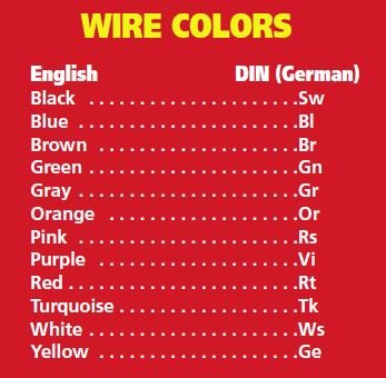
These codings sometimes confuse people: GRSW or GR/SW or GR-SW. Do not confuse WS and SW. SW means black. WS means white. GR (GRAY) does NOT mean green. Descriptions MAY have the first letter capitalized and the second letter in lower case; Sw means the same thing as SW and vice versa.
Two color wires MAY, AND USUALLY DO, have the main wire color correspond to a normal broad-based function, and the stripe has a sub-function. Thus, a brown wire with a yellow stripe has some sort of function related to brown (a grounding function) ...and in practice, a brown wire with a stripe is not directly mechanically nor electrically grounded ....it might go to a switch, or anything else, and the other side of that 'something' is directly grounded. Note that when saying something is grounded, or directly grounded, that means that the connection under discussion connects to the vehicle's engine, transmission, frame, etc...that is, the metal cases, etc. This is a very good thing, and just ONE reason is that you can be SURE that any SOLID brown color wire is ALWAYS a REAL and DIRECT ground. The BMW method of using wire colors and stripe colors is much more precise than the old American cars and bikes methods. Note that in the metric system, BROWN means Earthing. Note also, that the system used in home or other buildings is slightly different in SOME wire colors, compared to vehicles.
In many instances, a color, as described below the Wire Colors chart just below, will, if used as a stripe, identify a function quite nicely. A bit of thinking will be helpful.
Transparent, TR or Tr, is almost never used in vehicles, and is not listed above, but is, below.
The following colors are for the main body color of the wire, and usage are examples:
BL blue...usually, not always, oil pressure, ALT (GEN) lamp; alternator.
BR brown...always the ground, battery negative, frame ground.
GE yellow...low beam.
GR grey (gray)...rear lights.
GN green...usually, not always, switched power, from the ignition switch to the ignition coil.
RT red...battery, usually NOT fused, usually NOT switched, and comes directly from the battery.
SW black ...usually, not always, the starter, and some functions to the ignition coil, starter, tachometer.
VI violet ...almost never used as a body color, usually as a stripe. On Airheads, it is usually a GN/VI wire, that is used to supply power to the coil of the headlight relay.
WS white ...high beam.
TR transparent ...very seldom used ...and very unlikely to be seen on a vehicle.
Here is a link to an article on the https://airheads.org website that explains colors and function differently, and includes color sketches and more descriptions of functions:
This is one I wrote: https://www.airheads.org/tech-tips/electrical-wire-upgrade/
This one has illustrations of the wires/coding, ETC
https://www.airheads.org/tech-tips/wiring-color-codes/
More descriptions follows in the next section, below.
BOSCH ....and....most other manufacturers ....device connection number/letter codes:
These numbers/letters are found printed or stamped/engraved on all sorts of electrical devices in your motorcycle and are found in schematics, on connection boards, switch terminals, relay terminals, etc. This is a comprehensive list, and it combines Bosch published codes and the specifications in DIN 72552, thus some listings will have 1 or more possible functions/devices. This list covers far more than what is usually used on most BMW vehicles. Rarely there is found ambiguity in actual use. The actual total list of all possible connection codes is MUCH longer than on this page. Letters are added to the single or twin numbers to identify particulars.
1 Ignition, coil, primary, breaker, low voltage, distributor. In practical use, the ignition points and the condenser have black wires. In addition, the connection to a tachometer will come from the condenser and points via a black wire, and if there is a jumper wire between coils, it is also black.D- Alternator/generator negative. This is usually a brown wire going to the chassis.
D+ Alternator/generator system + output (for alternators, it is the diode board output). Usually a red wire.
Df Alternator rotor and generator field connection. Usually blue/black.
U, V, W: Alternator 3 phase connections.
Y Alternator field center-tap, used on Y type windings (not possible on delta windings)
On most alternators, the stator is stationary and may be called a field.
B+ Battery +; also used for + input on voltage and/or current regulator.
B- Battery negative (-)
Directional signals (see 49 a,b,c, above):
C First indicator lamp
C2 Second indicator lamp
C3 Third lamp
L Turn signal, left side
R Turn signal, right side
KBL Usually the flasher relay output, that connects to the indicating lamp. Usually black/white.
NOTE: Right directional lamps have a blue/black wire; Left directional lamps have a blue/red wire.
For more details on the pin numbers of parts, particularly relays, sketches, diagrams....etc, see: http://www.e38.org/understanding euro wiring diagrams.pdf
NOTE! There are instances in which original assemblies, such as the left switch gear on the /6 Airheads, are no longer available. BMW will substitute something in many instances, but you may need additional information on the changes. A wire color may be modified, or a wire added that you use differently. As an example, when replacing the left side of handlebars assembly, you might want to refer to item (6), in the following article: https://bmwmotorcycletech.info/misclelectrical.htm (that is article 38B). You will find more information on a variety of things-electrical, in articles 14, 15, 24B. USA and Euro versions may be considerably different, particularly in the handlebars switch gear.
This area reserved for a future update on how to interpret certain terminal numbers and colors in actual practice, on such as the connection board inside the headlight bucket of your Airhead.
SOURCES for small amounts of color-coded wires. You can always get used wires from wrecked cars ...but new is much nicer!:
1. http://riwire.com good solid source
2. https://prowireusa.com some interesting stuff, including build-your-own stripe color, they will make it.
2. ASK on the Airheads List
Many autoparts stores have smallish to medium sized reels of various wires, and I have seen this for American gauges and metric wires, in various colors. It is difficult to find small amounts of the striped color coded wire you may need for your motorcycles.
Two wire charts, ...confusing? maybe ....but see BOTH:
Below is a much more detailed chart on wire details. MUCH of this first chart (of two charts) is nerdy information, unlikely to be of much use to you. Note that the 'Maximum amps for power transmission' is very conservative, and can almost always be exceeded by a considerable amount in practical use, in particular for short lengths of wire. Rated capacities for wire are, in any case, rules-of-thumb, although there are standards for such as house wiring. Values in the below table for maximum amperes need to be used in conjunction with just how you intend to use the wires: bundled? solid wires? stranded wires? open air? temperatures? and other factors.
For motorcycle use, the below table #1 is quite conservative. Note again what I said above, about short lengths of wire. With short lengths, the heating effect, and the voltage drop, can be so low as to not need nearly the large size of wire as the chart shows. In fact the column for Maximum amps for chassis wiring is often considerably still too conservative.
In the AWG gauge column are also listed some metric sizes, which are actual metric GAUGE sizes. These are NOT the sizes for wires as used by BMW in its wiring diagrams, they are listed here to cause confusion (well, not, but they do/can). In BMW vehicle diagrams, the wire sizes are conductor diameters in effective mm squared; the chart below has the value in its diameter ...see that third column, below. NOTE that this is a chart of absolutes, regarding SIZES. In practice, one should use a larger gauge in most instances....see the equivalents noted very early in this article, for those practical gauge equivalents to mm sizes. While you are unlikely to see this, note how the very small metric sizes are named, near the bottom of the chart, in the AWG vertical column! This very small wire is used in such as winding transformers, etc....and is where Metric sizes get confusing! Yes, this is all very nerdy information!
Table #1
|
|||||||||||||||||||||||||||||||||||||||||||||||||||||||||||||||||||||||||||||||||||||||||||||||||||||||||||||||||||||||||||||||||||||||||||||||||||||||||||||||||||||||||||||||||||||||||||||||||||||||||||||||||||||||||||||||||||||||||||||||||||||||||||||||||||||||||||||||||||||||||||||||||||||||||||||||||||||||||||||||||||||||||||||||||||||||||||||||||||||||||||||||||||||||||||||||||||||||||||||||||||||||||||||||||||||||||||
Table #2
Hopefully this table will explain a few things better, but it is still a bit nerdy. This table includes the cross-section (mm�) information; and that AWG sizes as large as 6/0 are included. The below table gives closest equivalent size cross references between metric and American wire sizes. In Europe, wire sizes are expressed in cross sectional area in mm� and also as the number of strands of wires of a diameter expressed in mm. For example 7/0.2 means 7 strands of wire each 0.2mm diameter. This example has a cross sectional area of 0.22mm�. In America, the commonest system is the AWG numbering scheme, where the numbers are applied not only to individual strands but also to equivalent size bunches of smaller strands. For example 24AWG could be made of 1 strand of 24AWG wire (1/24) or 7 strands of 32 AWG wire (7/32).
|
AWG Number |
� [Inch] |
� [mm] |
� [mm�] |
|
6/0 = 000000 |
0.580 |
14.73 |
170.30 |
|
5/0 = 00000 |
0.517 |
13.12 |
135.10 |
|
4/0 = 0000 |
0.460 |
11.7 |
107 |
|
3/0 = 000 |
0.410 |
10.4 |
85.0 |
|
2/0 = 00 |
0.365 |
9.26 |
67.4 |
|
1/0 = 0 |
0.325 |
8.25 |
53.5 |
|
1 |
0.289 |
7.35 |
42.4 |
|
2 |
0.258 |
6.54 |
33.6 |
|
3 |
0.229 |
5.83 |
26.7 |
|
4 |
0.204 |
5.19 |
21.1 |
|
5 |
0.182 |
4.62 |
16.8 |
|
6 |
0.162 |
4.11 |
13.3 |
|
7 |
0.144 |
3.66 |
10.5 |
|
8 |
0.128 |
3.26 |
8.36 |
|
9 |
0.114 |
2.91 |
6.63 |
|
10 |
0.102 |
2.59 |
5.26 |
|
11 |
0.0907 |
2.30 |
4.17 |
|
12 |
0.0808 |
2.05 |
3.31 |
|
13 |
0.0720 |
1.83 |
2.62 |
|
14 |
0.0641 |
1.63 |
2.08 |
|
15 |
0.0571 |
1.45 |
1.65 |
|
16 |
0.0508 |
1.29 |
1.31 |
|
17 |
0.0453 |
1.15 |
1.04 |
|
18 |
0.0403 |
1.02 |
0.823 |
|
19 |
0.0359 |
0.912 |
0.653 |
|
20 |
0.0320 |
0.812 |
0.518 |
|
21 |
0.0285 |
0.723 |
0.410 |
|
22 |
0.0253 |
0.644 |
0.326 |
|
23 |
0.0226 |
0.573 |
0.258 |
|
24 |
0.0201 |
0.511 |
0.205 |
|
25 |
0.0179 |
0.455 |
0.162 |
|
26 |
0.0159 |
0.405 |
0.129 |
|
27 |
0.0142 |
0.361 |
0.102 |
|
28 |
0.0126 |
0.321 |
0.0810 |
|
29 |
0.0113 |
0.286 |
0.0642 |
|
30 |
0.0100 |
0.255 |
0.0509 |
|
31 |
0.00893 |
0.227 |
0.0404 |
|
32 |
0.00795 |
0.202 |
0.0320 |
|
33 |
0.00708 |
0.180 |
0.0254 |
|
34 |
0.00631 |
0.160 |
0.0201 |
|
35 |
0.00562 |
0.143 |
0.0160 |
|
36 |
0.00500 |
0.127 |
0.0127 |
|
37 |
0.00445 |
0.113 |
0.0100 |
|
38 |
0.00397 |
0.101 |
0.00797 |
|
39 |
0.00353 |
0.0897 |
0.00632 |
|
40 |
0.00314 |
0.0799 |
0.00501 |
Revisions:
09/19/2009: Add hyperlink for euro wiring sketches & diagrams. Add note regarding airheads.org article on Joe 'Cuda's article.
01/14/2012: Add commentary & add chart & commentary for metric versus American, etc.
08/11/2012: Clear up possible misunderstandings about how the colors are used when there is a stripe. I have been informed that Joe 'cuda's article was removed from the .org website. Added note.
10/15/2012: Add QR code, add language button, update Google Ad-Sense code.
11/05/2012: Edit & add more material. Remove information on Joe Cuda's article, which is no longer on the Airheads.org website (it was very good).
11/06/2012: Add discussion section at beginning of article.
04/23/2012: Change wording, slightly, about "German Metric System"; minor other changes.
06/14/2013: Add Sources.
06/29/2013: Try to clarify the differences between American & Metric wire codes & sizes. Add table #2.
08/28/2014: Add link to Joe's article on Airheads.org.
04/30/2016: Begin update of article. Update meta-codes, layout, left justification for all, add viewport code, clean up explanations, combine sections, etc.
01/19/2017: Metacodes, scripts, html cleanup.
03/04/2017: Prepare for inserting information on headlight bucket board and interpreting terminal numbers and colors in actual practice, and add a paragraph on replacing left switch gear on /6 (where to find the information on this site), etc.
06/03/2018: Major html, etc..,cleanup. Purposely left technical details colors but clean up code for them.
08/29/2018: Quite a few things clarified, including green and green/blue and red wires. Also added information to the Bosch wire/terminal numbers descriptions (numerous).
12/20/2020: Minor updating.
11/07/2023: Update wire availability list area.
08/06/2024: Minor update on wire source list
� Copyright 2024, R. Fleischer
Return to Technical Articles LIST Page
Last check/edit: Tuesday, August 06, 2024