
|
|
Tachometers.
REPAIRS. CALIBRATION. PROBLEMS.
Connections & wire colors. Schematic and other diagrams.
Retrofitting Electronic Tachs to earlier
models with mechanical tachometers.
Applies primarily to Airheads (If you are truly nerdy, read this entire article, as information for calibration methods for all engines near and at the very end).
PART 1. REPAIRS TO ELECTRONIC TACHOMETERS.
HOW TO FIX one style of BMW ELECTRONIC TACHOMETER AS USED ON AIRHEADS.
Example: Typical symptoms: ...jerky readings, wrong readings, irregular wrong readings, jumpiness may be mixed.
Problems with jumpy and often quite high readings, intermittent, irregular, etc., can be due to poor connections at the coils, and/or poor grounding, particularly the system secondary ground at the front coil bracket. Often the tach will read considerably high at idle rpm; middle rpm may be relatively OK; then as rpm rises, maybe around 5000 RPM and upwards, the tach may read quite high. USUALLY the problem is bad capacitors inside the tach, relatively easily replaced. The capacitors can usually be measured while still in-circuit, but this depends on your capacitance tester. Be very careful, it may be best to unsolder capacitors, at least at one end, and then use a capacitance checker.
Problems in bike's wiring &/or in the ignition circuitry; even some green corrosion in the ignition coil towers or kill switch, etc., can cause weird readings ...be sure those are not the problem! Only good way to be sure the KILL switch is not at fault is to bypass it, temporarily ....although if cleaned, and then symptoms gone, you found the problem. Green corrosion is particularly annoying and problematical, as it can help create a 'diode effect'.
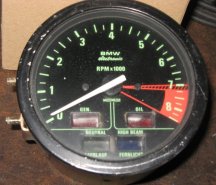
All the BMW electronic tachometers that I have seen open, so far, are all somewhat similar in circuitry design. For this particular how-to-fix section PART 1, an R80ST tachometer, Motometer type 5440108500 was used. Other styles of tachometers are described in Part 2.
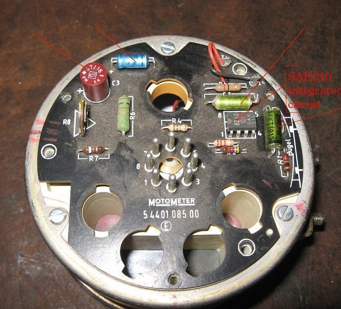
In the above photo of the printed circuit board, 4 long red lines indicate the various capacitors. Disregard the short three lines area on the left, they were added by me for case parts alignment.
Remove rear 3 screws, any gaskets, etc. Unsolder black & red wires. Black went to - terminal; red to + terminal, as shown above & marked on the printed circuit board. The black and the red wires are the meter movement itself.
Using the following circuit, which requires you to obtain the battery, resistor, and pot (potentiometer/rheostat), rotate the pot. from one end to the other. The tachometer must smoothly change readings. The circuit values in the sketch below should be adequate to ensure the tachometer can read from near zero to at least maximum. If the tachometer is jumpy, be sure it is not the potentiometer. If jumpy, the tachometer "meter" either must be repaired (if you can find a place to do that); or, you must obtain another entire tachometer, or, the face unit section.
For the Nerdy: the meter requires 1 milliampere of current for each 1000 RPM indication. Thus, if your maximum dial indication is 8000 RPM, 8 milliamperes is required.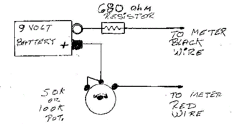
PARTS LIST:
YOUR tachometer may have different values, and could have different layout and connections.
The capacitors are the common failure items. Replace all 4 of them; or, remove, test, & replace the bad one(s).
C1 is 2200 pf, 400 volt rating
C2 is 0.15 mfd
C3 is 47 mfd, 16 volt rating
C4 is 22 mfd, 10 volt rating. The meter has built-in mechanical damping, C4 provides additional damping.
It is highly unlikely any of the resistors (or the calibration potentiometer) will fail.
R1 is 30 Kohms
R2 is 4.7 Kohms
R3 is 2.2 Kohms
R4 is 180 ohms
R5 is 82 ohms
R6 is 100 ohms, rated 1 watt
R7 is 39 Kohms
R8 is 47 Kohms calibration potentiometer
The Monolithic Integrated Circuit is a type SAK215, an 8 pin dual-in-line package. It is a pulse shaper and driver (it also counts pulses and converts the count to current) for the meter movement, and was designed specifically for tachometers.
http://pdf.datasheetcatalog.com/datasheet_pdf/micronas/SAK215.pdf
The circuitry in YOUR tachometer will NOT be exactly the same as the circuitry in that datasheet.
ZD1 is a 6.8 volt zener diode. A zener diode maintains a constant voltage across it.
Of the 8 pin connector:
Pin 1 is high beam lamp.
Pin 2 is connected to the illumination lamps circuit in the motorcycle.
Pin 3 is neutral lamp (ground it to illuminate the lamp).
Pin 4 is GEN lamp (ground it to illuminate the lamp).
Pin 5 is the connection to the trigger for the tachometer (points in points models; Ignition module in 1981+ models). Usually black wire.
Pin 6 is connected to +12 volts in the motorcycle & connects to the 4 lamps noted, & also connects to the tachometer illumination lamp. Pin 6 is often connected by a green/black wire to the +12 system.
Pin 7 is OIL lamp (ground it to illuminate the lamp).
Pin 8 is ground connection to motorcycle ground (-12v)
Clean the colored lenses from the inside after lamps are removed. Use Q-tips or similar, moistened slightly with ordinary household isopropyl rubbing alcohol.
Determining if the zener diode has failed is usually made with an ohmmeter or diode tester, but can be done, if the tach is plugged into the harness, by using a voltmeter across it. Determining if the integrated circuit has failed is best done by a seriously well-qualified electronics technician. A slip with a probe can fry this device.
One can use the motorcycle engine, running, to provide the pulses needed for the tachometer; one can calibrate the tachometer by other means too. One can also use any common audio amplifier, with a small transformer; in turn driving a circuit with a series capacitor, and a diode to ground, and a capacitor across that. This will form triggering pulses.
I don't really get into that method here, as it is for the more nerdy electronics technicians types.....although I do provide a table-top poorly-done sketch (scan of some old work of mine)....much later in this article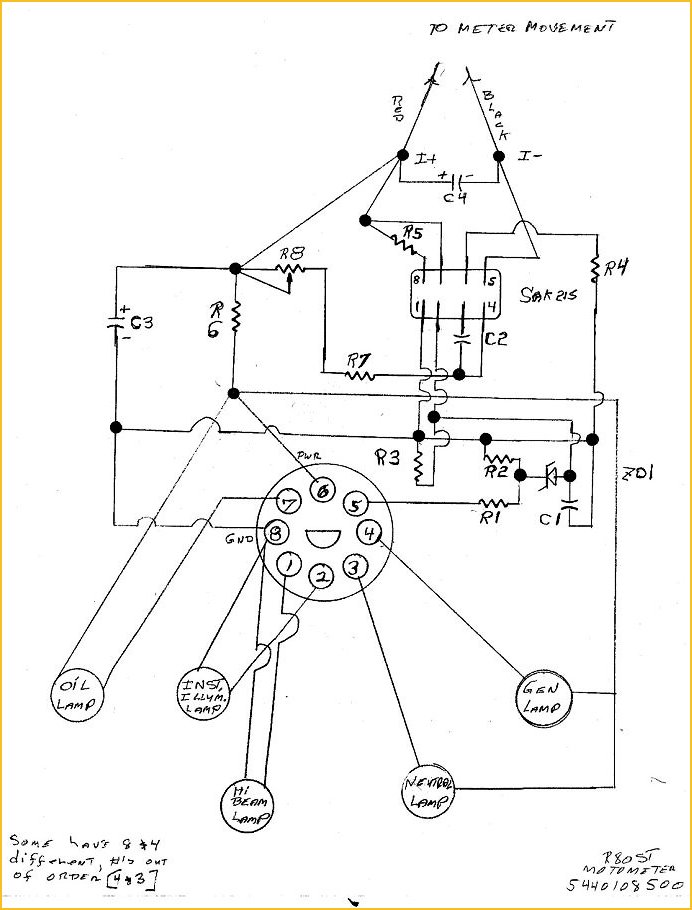
More in information is in PART 2, below.
PART 2. Everything Else:
In most of the old style instrument pods with a combined speedometer & electronic tachometer, there is NO male plug for just the tachometer. The tachometer assembly for these has 3 very thin wires coming out of it. BMW has not published those wire colors on their schematic diagrams. The wires are brown, green, and red. These colors correspond to brown being battery negative or chassis ground; green being signal from the ignition; and red being +12 volt power. These are standard industry-wide colors for those functions. FYI, brown signifies EARTH, another way of saying electrical ground.
The METER of these dual instrument pods tachometer has red & black wires going to the circuit board, red for + and black for -. That is the same as the R80ST Tachometer, in PART 1.
From the tachometer assembly, you will find the mentioned three wires to male spades in the instrument housing board. Brown to #12, green to #10 and red to #8. DO NOT REVERSE NOR MIX UP THOSE WIRES.
BMW installed 1 of 3 types of instruments on the Airheads. The first type is the combined speedometer/tachometer in the headlight bucket, as on the /5 models. Those are both fully mechanical items. You can check the calibration of these by various means. The best method for the speedometer & odometer is to use a GPS on a straight section of road. The tachometer can be checked by the methods outlined later in this article.
The second type of instruments began with the /6 series. Early versions of these had mechanical tachometers. This type of pod has round tachometers & speedometers, both together in one dual cavity black plastic case. There is a squarish black rubber multiple electrical connectors plug that presses into the rear of the pod; this has 1 small phillips style screw in its center, that fastens into PLASTIC. DO NOT over-tighten it. Note that BMW included some of the electronic tachometer wiring in the bike's harness for 1 or 2 years before the tachometer was actually changed to electronic.
For the ELECTRONIC tachometer version, inside that black rubber plug the pertinent wires for the tachometer are:
Pin 8 is a green/blue wire & is the battery power for the tachometer & some of the lamps in the instrument pod.
Pin 10 is a black wire & is the signal from the ignition system.
Pin 12 is a brown wire. Solid brown colored wires on all BMW vehicles are the same as battery negative, chassis ground, case ground, earth, etc. These correspond to the same colors inside the pod.
Note that two of these wire colors are very different from the standard tachometer internals (inside the tachometer itself) wires.
The third type of instruments was first used on the 1979 R65 & then on models such as the R80ST, R80G/S, & then on SOME others. This type uses ROUND EXTERNAL PLUGS & is quite different internally for parts physical layout. The TACHOMETER itself is similar in electronics/wiring, but the exterior PLUG connections are quite different:
Pin 8 is a brown wire; this is the ground (earth) or battery negative.
Pin 5 is a black wire; this is the signal from the coil.
Pin 6 is a green wire; this is the +12 power.
Although the PLUG & cases are different, the electronic tachometer is basically the same electrically & electronically, but physical internals are laid out differently.
(1) Tach installation information:
THIS INFORMATION IS PRIMARILY FOR YOU IF CONVERTING A MECHANICAL TACHOMETER INSTRUMENT POD TO USE AN ELECTRONIC TACHOMETER. IF your bike already has an electronic tachometer in the pod, this is reference material.
Use BMW Service Information bulletin, dated May 1978 #1063R; which deals with installing an electronic tachometer into the pods that came with mechanical tachometers. The information applies to all models at that time, which were R60/6 through R100RS (~1977). In some instances you have to drill two holes for a wire. BMW says to use 2.6 mm. Nothing critical about that. BMW began to install wiring to the instrument pod in order to accommodate the electronic tachometer at least a year or two, BEFORE those electronic tachometers were actually installed by BMW.
If the black lead from terminal 1 of the ignition coil (points connection) does not exist in the pod, then you need to drill the holes. If the black connection is present, it will be known by an actual connection at pin position #10 of the 12 pin plug.
The tachometer wiring is:
red = +12
brown as usual is ground (same as battery negative or chassis, or engine case, etc.)
green = signal, connects to ignition coil terminal that the points connect to.
1977 bikes: if no pin #10, nor wire to coil, neatly find a way to lengthen the green wire & connect to the points connection on that particular coil.
BMW has a seal available to block off the mechanical tachometer takeoff area. The worm, etc., at the engine case, is left in place. The seal is 63-23-1-351-257.
For bikes with the pod style 2, the electronic tachometer will be, for some models 62-13-1-243-434. Tachometers for various bikes and years come with different dials and markings, and thus have different part numbers. Check common dealership fiche for yours. In any event, the tachometer is a very pricey part, & a good used item can be considered. Note that any tachometer specified to work on a Harley Davidson "dual fire", such as Drag specialties or similar, will also work OK on any wasted spark Airhead ignition, but trying to put such into the existing pod will be 'interesting'.
Do not depend on your year, 1977 or 1978, for your bike. BMW begins production of the following year's models immediately after the annual month-long vacation in August and there can always be anomalies. It is easy to see what is inside your pod, and the color of the pointer, dial, and where the yellow and red portions begin ...etc.
(2) Tachometer calibration check (Any tachometer version):
Harbor Freight Company has at least two types of tachometer calibration instruments, that are not expensive, that can be used ...but ...the method shown below is useful for just about any engine and is very accurate, and may cost you nothing. You can use my method to adjust the rpm of an engine, perhaps even your lawnmower's rpm governor; & you can use it to check tachometer calibration.
No matter what type of tachometer you have, mechanical or electronic, what follows is a simple way of checking the calibration of your tachometer. This method works with nearly anything that rotates. This method is typically more accurate than tachometer checkers. It can be comparable, or better, to a quality electronic impulse counter.
It is so accurate that you can totally disregard that it could have any error.What you will do is to take advantage of the extreme accuracy of your electric power line alternating current frequency. The frequency is held very precisely to 60 Hz (Hertz) in the USA (aka '60 cycles per second' or cps). Old-fashioned motor-driven clocks were powered by that, & kept perfect time for years. If you are in a Country with 50 Hz power, you need only to slightly change the number of lines and calculation, which is explained later.
What follows is specifically for the Airhead Boxer Twins, but is adaptable to any engine where you can get to the crankshaft ...and the procedure can be modified to work with the camshaft instead of crankshaft, because the camshaft rotates at half the RPM of the crankshaft.
Disconnect all battery negative wires first. Then remove the front cover of the engine. Disconnection is done to prevent damage to the stock diode board as you remove the cover. Reconnect the battery (disconnect again when done before replacing cover).
Clean the flat end of the alternator rotor, & mark that end with SIX (6) white paint lines radially, at ~ 60� apart. Try to keep them thin & reasonably straight & from the center outward. You can use white permanent paint or whatever you want. Sometimes I make up a small piece of black paper with white lines, & use fast drying rubber cement to hold the paper to the end of the rotor. The results, from whatever method you use, is a stroboscopic disc. Some have made proper depressed center discs of metal, using the existing alternator rotor bolt.
If you love tools I suggest you make the disc of metal or some insulating medium, of decent diameter so it is easy to read, paint the disc flat black, & paint or engrave the thin white lines. Dish the center if you want to. Put a hole in the center, & you may or may not need to obtain a longer than normal alternator bolt, modifying it so it works like the original bolt. I suggest you make the bolt from a 8.8 grade or high material. Make a round stepped spacer of insulating material, such as from fiberglass rod, to space the disc away from the alternator and not make metallic contact with the end copper of the rotor. You could make this of metal, if paying attention to the rotor end flat electrical area. The part that fits into the rotor recess is hardly critical in diameter nor depth. Perhaps 0.550" diameter, and you do not have to make it a stepped part. I made one for someone that was nothing but a piece of 1/2" diameter brass rod, with a hole in the center. You need not use more than a light torque on the bolt (a few foot-pounds is enough for this), as it is the taper fit of the rotor to the taper of the crankshaft nose that keeps the rotor from coming off. NOTE that the bolt must have some of its threads removed similarly to the stock bolt so it actually tightens by screwing into the CRANKSHAFT, and not the rotor just like the original. The bolt is longer by the thickness of your spacer plus thickness of the disc. Nothing critical. Don't forget to later re-install the original bolt, torquing to minimum side of specifications.
I have a friend who loves tools. He has a vast collection. He made a large diameter disc with a step on the rear and inserted a plastic electric insulating spacer. After he made the disc, he painted the disc flat black epoxy. After the paint hardened he used a milling machine divider table and teensy rotating end mill, to make the 'lines' ...maybe 1/8" wide ....all precisely at 60 degrees. No need to do all this, but he appreciates nice tools. He filled in the lines area with white epoxy paint. Lovely thing.
I simply use a fine artists brush & white fast drying paint, or chalk, or old-fashioned tailor's marker, & mark the end of the stock rotor. I also use to have an old engine cam degree wheel that I put the radial lines on the unused reverse side of the degree wheel. I gave it to someone who lusted after it.
Old-fashioned fluorescent lamps (long tube types) turn on & off with power line voltage changes from + to - to +, etc. The powerline electricity is called A.C., which means it is an Alternating Current, which goes through a complete cycle of: off; on-positive; off, on-negative, and back to off .... all this 60 times per second. This rate is said to be 60 cps (cycles per second) or 60 Hz (Hertz) per second. Since the light is off twice, that means 120 light flashes PER SECOND for USA 60 Hz power.
These old-fashioned fluorescent lamps are actually gas discharge lamps, the electrical discharge causes phosphor coating on the inside of the glass to light up. This happens very fast. The flashing occurs so fast that our human eye & brain do not distinguish the multiple flashing as such, but see only continuous light. The picture on your TV screen flashes its picture too, at 30 times a second in the USA.
It is the stroboscopic effect that causes spoked wheels on cars to look crazy, even rotate backwards sometimes in movies, due to the rotating camera shutter rpm. My suggestion is to use a CFL lamp, and have it mounted in a protective holder. Only some coiled (CFL) fluorescent lamps also do this flashing with the power line, but many do not. I can offer no hard and fast rules for make nor model of easily available CFL lamps. I tested several CFL's until I found one that worked in synch with the power line. I simply put a standard TURNTABLE measuring strobe disc on a turntable, powered the turntable, and shined the CFL on the strobe disc. If it showed very distinct lines, then I knew the CFL was THE ONE. My long fluorescent tubes in the shop work fine too ...but you need the shop a bit darkened, and they point downwards. Best to have a proper lamp on a drop cord, or something ....so you can bring it close to the engine. The coil type of CFL fluorescent can be a small one, and fit into a common drop cord lamp end, and so is protected against breakage. It's worth finding a proper CFL lamp.
No, you can NOT use 12 volt powered fluorescent lamps.
Incandescent (heated filament) lights have fluctuating light output changes, but the heated filament heating/cooling and thus change of brilliance is a very low amount ....almost no change in effective light level happens, so common incandescent lamps are quite poor for strobe effects usage. Old-fashioned neon lamps work well, except the light output is low over-all.
Your disc, or painted lines on the rotor, will simply be illuminated by your stroboscopic light source.
When the engine is started, shine the stroboscopic lamp on the strobe lines you made, & watch the markings. There will be SIX, appearing to be fully stopped from rotating, at precisely 1200 rpm. Same at twice & at three times that rpm, and so on. Check your instrument pod's tachometer reading!
This means that using 6 lines you can check your tachometer or engine rpm at 1200, 2400, 3600......
Note that you do not have to use 6 lines, in fact you can use one, two, three, or four. You just need to know how this all works, and how to interpret the results.
An example and explanation:
Let us imagine that instead of six marked lines you have just a single white line on the rotor's end, radially from the center to one side, and that the engine is rotating that crankshaft-affixed rotor at precisely 1800 rpm. You will see four lines illuminated by the strobe lamp. Why?
1800 RPM means 1800 revolutions per every 60 seconds. So, dividing, you have 1800/60, or 30 revolutions per each second of time. Because the lamp is flashing exactly in accordance with the power line rate, every second the light is flashing 120 times. Remember: 60 Hz x 2. Thus, 120/30 is 4 lines appearing to your eye. If the rotor is at a slightly higher or lower rpm, the lines will appear to rotate in one direction or the other (slightly higher rpm causes lines to advance with the movement).
So, what about 2400 rpm? Same mathematics applies, & you get THREE lines.
So, while you do not have to mark 6 lines. I suggest you do, as it is very convenient.
Some countries use 50 Hz; what do YOU think the number of lines and rpm for FIVE lines should be??? Go back a few lines re-read three times ....and THINK!
In practical use: Note the electronic or mechanical tach error, if any. I suggest you check the tach at several points. Just what points you check, depends on the number of lines you painted or otherwise made; and, if you have 60 Hz or 50 Hz power. Perhaps you want to check the tachometer at 1200 rpm, & then multiples of 1200. I do suggest that you check the tachometer near yellow/red line areas, as those are critical for engine life/safety. Since every multiple of 1200 will produce the same indication (of sorts), the rpm's for 6 lines (USA 60 Hz power) are: 1200, 2400, 3600, 4800, 6000, 7200. Watch the strobe & perhaps have a buddy watch the tach, as the RPM is increased.
If you have been thinking way ahead, yes, you could mark your teeth on the flywheel ....but they are an odd number of teeth, but being off slightly would be OK. You can even mark the wheel spokes and count wheel rpm, and apply with gears numbers.
The method will also work on any engine where you have no access to the crankshaft, but will have access to the camshaft drive. For most engines, the CAMSHAFT will rotate at EXACTLY one-half of crankshaft speed. Thus if you can get a radial disc, paper, metal, drawn lines, whatever, on the camshaft, you can read the effective crankshaft rpm by simply multiplying by 2. This works pretty well for the early Airheads, and some other bikes.
BTW....you can watch the function of the ATU using the strobe method, but for that, use a strobe timing light, triggered from a pickup probe clamped around an ignition wire. In the same way, you can actually 'stop the movement' under the strobe light, of such as valve rocker arms, valves and valve springs, etc. Shine your timing lamp on these areas, and adjust engine rpm. Have fun!
(3) Truly nerdy stuff.
Three pages of scans from my scribbled notebook.


rev: � Copyright 2024, R. Fleischer
Return to Technical Articles LIST Page
Last check/edit:
Friday, July 05, 2024
03/16/2006: Add calibration information + minor editing for clarity.
01/14/2009: Was 38A.
06/14/2009: Minor type fixed; plus add information on use of CFL's.
02/15/2012: Chk article, particularly to be sure the strobe lamp usage is fully explained.
08/25/2012: Add note at top to avoid confusion about tach wires colors & pod connector colors, etc.
10/15/2012: Add QR code, add language button, update Google Ad-Sense code; clarify some details. At a later date, in 2013, the language button was removed due to javascript problems in some browsers.
10/25/2012: Revise for clarity; add information for color coding & pod plug & spades information for both types of pods; clear up confusion on not only the two pod types of wiring, but the meter, the plug pin differences, & the 'factory conversion' information. Add Other engines section.
02/13/2014: Revise entire article for clarity; include /5 notes too.
09/18/2014: Revise for smaller screens & again improve clarity in a few areas.
12/19/2015: Begin to: Update meta-codes. Add REPAIRS. Condense & clean up. Add section on use of the flywheel (clutch carrier).
12/20/2015: Finish.
04/02/2016: Update metacodes, layout, colors, fonts, etc.
12/03/2016: Metas, scripts, HTML excesses, layout, explanations improved.
05/28/2017: Clean up excessive colors and fonts.
05/02/2018: Reduce HTML, colors, fonts. Improve layout. Improve explanations slightly. Clean-up.
05/28/2018: Clarify that one must unsolder the meter movement black and red wires; and some text updates.
05/30/2018: Add schematic diagram.
07/05/2024: Update article, including adding a new section, number (3).