|
|
The BMW Airhead Oiling System
Sketches, descriptions; caps; thermostats;
oil breather ...etc!
Note: For history of this website, future, and information
about donations: CLICK!
� Copyright 2024, R. Fleischer
https://bmwmotorcycletech.info/oilsketch.htm
50B
This article is expected to be used together with article 50A. https://bmwmotorcycletech.info/oilingsystem.htm
I suggest you find the time to read all articles from #49 through #51D.
First sketch is of an EARLY Airhead oiling system, all models from the /5 through approximately 1979. This sketch is from a BMW Factory Service manual.
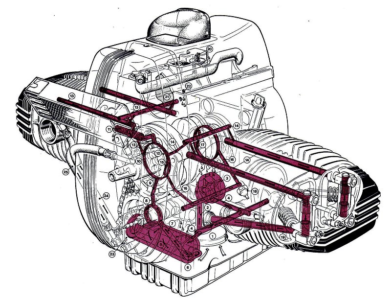
Description of the above early system, through ~1979.
NOTE that most, but not all of the items, apply to ALL years & models.
Contrary to wrong translations, etc, the system is actually what is called
a Full Flow type, as opposed to a pure bypass type (which only happens
on these motorcycles if the emergency bypass valve at the inner wall of
the oil filter chamber opens). The cooler system IS a bypass system.
|
Sketch item # |
Description |
| 1 | Oil strainer pickup in engine oil sump |
| 2 | Pipe from above strainer to oil pump |
| 3 | Oil pump, Eaton-type. The center drive of the pump, which is attached to the rear end of the camshaft, is different on early & late models. In the pump area there is an index mark to line up and the vane has one inner edge chamfered, which goes on first. You MUST replace the O-ring if the plate is removed. I use a wee drop of Loctite BLUE on each clean and dry screw or bolt and female thread. The early plates, which used a screw & not a bolt, should be changed to the later type ...the groove depth was changed too, so change the early plate to later type, and use the later bolts. |
| 4 |
High pressure oil pump output, note the two engine plugs in the passageway. This output goes to the oil filter canister. Note that this oil goes to the OUTside of the oil filter. Occasionally these external plugs will weep or leak a small amount. To replace the plugs you MUST first heat the area rather hot. I suggest you do NOT re-use the original slotted type of plug, it is NLA anyway. Be sure plug and associated engine threads are clean and dry, use a strong solvent as required. Use a couple of drops of very strong Loctite on the threads before assembling. I like to tighten the plugs immediately after I re-heat the case area and have applied the Loctite.
Do not overtighten. ~12 footpounds is enough. The earliest plug had a single slot for a common screwdriver, 11-11-1-259-077, and is NLA, do not use them. The next type was an allen-recess plug, which is stronger, it is M12 x 1, 11-11-1-338-645, and used up to July of 1991. Then, BMW changed the machining at the area, and installed a 11-11-1-338-756, which looks like a small drain plug, & is quite strong. It is used with a solid gasket which is 12 x 15.5 x 15, 017-11-9-963-130. |
| 5 | Oil filter canister and oil filter |
| 6
|
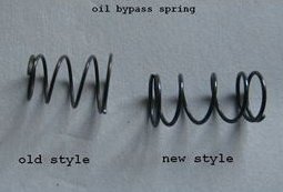
Oil pressure bypass valve located at the innermost end of the oil filter metal canister. The spring-loaded ball-check valve device allows unfiltered oil to pass into the engine from the pump & canister if the filter oil flow is blocked. It also allows SOMEWHAT of a bypass if the pressure is too high from such as cold thick oil, perhaps with higher rpm than idle rpm . This will not work well, and filters can collapse if the RPM used is too high during starting a quite cold engine. The oil pressure needed to begin to open the bypass ball check valve is said to be 21.76 psi. The factory service manuals will show 1.5 Bar, but some BMW manuals have WRONGLY converted that to psi. NOTE that this is DIFFERENTIAL PRESSURE, not 'the' pressure in the canister. The canister oil pressure is very close to the same as the pressure in the canister output to the rest of the engine. Thus, the emergency ball/spring valve sees approximately the same pressure on both its sides in normal cruising, etc. However, the ball and spring might activate under certain conditions besides a blocked filter. The oil pump is quite powerful, and there is only so much volume of oil that can, at any particular pressure, flow through the central pipe into the large passageway system...hence my belief that the ball valve could open. This is more likely to be so with cold thick oil and a sudden 'slug' of oil from the pump, upon start-up. Another thing is that since it is only a very thin layer of oil that actually does the lubrication and bearing cooling for the engine (particularly the mains and rods), getting the oil moving to those areas, which have a low clearance, is important at startup, and the bypass valve might help. BMW modified the outer plate on the GS models (which don't have the outer thermostatic plate and that plate's different oil passageways) to help prevent the slug of compressed air pushing the oil, thereby possibly damaging the oil radiator, upon starting, especially in cold weather, especially just after the cooler has drained during a filter change job...and if blipping the throttle. The associated bypass hole IN THE COVER is ALSO used to help keep the cooler pressure within reason on startup. The hole size was changed, so see the info on drilling yours, if it is the small early size hole. |
| 7 | Outlet of the oil filter canister, leading to the camshaft |
| 8 | 2.5 mm diameter bore passageway in camshaft flange |
| 9 | Oil from camshaft flange to engine front main bearing cap |
| 10 | Passageway with outlet (#16) to REAR main bearing and to the pressure release valve (#11) |
| 11 | Pressure release valve, opens above 5 BARS (75 psi). Excess output lubes the chain & sprockets area. Oil FROM this valve can be small to non-existent if the oil is hot and engine rpm is at idle, particularly so on a worn engine. Do not set idle rpm too low. 1000 rpm is nice. This valve very rarely has a problem, but there have been a few instances of it freezing open, so the pressure drops, and the oil light might not shut off, or, be irregular. |
| 12 | Front big end bearing shell, has outlets to #13 & #14 |
| 13 | Passageway to RIGHT cylinder head via the TWO top studs |
| 14 | Passageway to LEFT cylinder head via the TWO top studs |
| 15 | Bore IN THE CRANKSHAFT delivers oil to the LEFT big end. |
| 16 | Passageway to the oil pressure switch AND rear main bearing |
| 17 | Bore IN THE CRANKSHAFT delivers oil to the RIGHT big end |
| 18 | Oil pressure switch. The oil pressure warning lamp switch is not located in the part of the left side oil gallery you may think it is; so look quite carefully at the factory sketch. Rather, that switch is located in a different part of the oiling system ...MUCH farther down the line, actually in the gallery that supplies the rear main bearing. The pressure in the switch area is about 14.5-29 psi at 800-1000 rpm; and about 60-74 psi at 4000 rpm. These are official figures, and will vary rather a lot with oil temperature, type, grade, and switch. NOTE that very early Airheads had a tapered pipe type thread ...also note that the later switch is the same as mid-seventies 2002 BMW car sender. Do not use teflon tape on either switch. Do NOT mix up the switches. The later switch (from mid-seventies approx.) needs a washer. Mixing up the switches can ruin the crankcase. |
| 19 | Oil return from cylinder head via pushrod tubes & lubes camshaft lobes and lifters along the way |
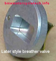
| 20 The disc style item should be checked for chipping, etc., whenever you are in the area or suspect excessive oil usage. Check the hole, item 22 below on 77+ models. |
Crankcase breather, disc style, later (1981+..??) was a reed valve. The round disc breathers measure 1.063" diameter (27mm), .063" thick, and the hole is 0.233. It's original part number was 11-11-1-251-229, and is obsolete. Be sure to read the information on the breather disc, and reed type, later in this article!
Source for brand-new old-style Airhead breather discs; free, including postage to USA addresses:
[email protected] |
| 21 | Oil condensing chamber |
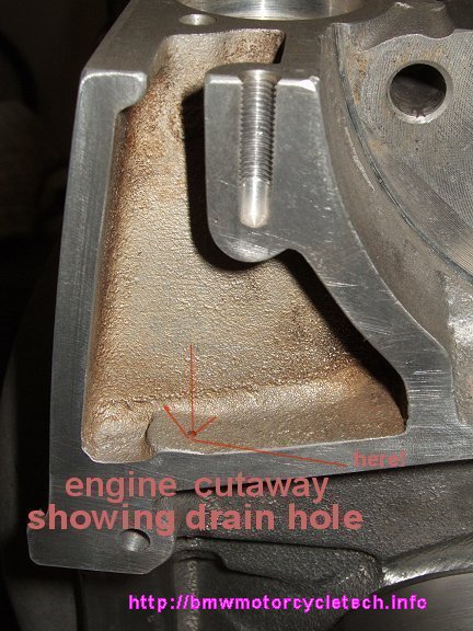
| 22 | 1977 model year and later (this means introduction was on the /7). 1.5 mm diameter hole in bottom of #21, Position in sketch not 100% accurate. Returns condensed oil to the crankcase. See photo below on engine cutaway photo. |
| 23, 24, 25 |
Cover for oil canister. Type shown is for the oil cooler model as shown; which incorporates cooler feed line #24 and return line #25. GS models will have a NON-thermostat cover. |
| Thermostat, on cooler models, when equipped with the thermostat type of cover |
The thermostat seldom fails. They have been known, RARELY, to stick. This does not have any real effect on engine oil flow. The thermostat is NOT simply an on-off valve. The valve inside it determines what percentage of oil is routed to the cooler. The thermostat is specified to begin to open at 80�C (176�F) and be fully open at 110�C (230�F). GS models without the thermostat use a sized hole to control the flow to the cooler. This method seems adequate. Do NOT use a lot of rpm when the engine and thus its oil, is at very low temperatures, as this will be hard on the cooler soldered/brazed seams. The GS cooler is supposed to be covered in really cold weather, to avoid overcooling the oil during riding. |
On all years and models, oil is additionally returned to the sump by the amount escaping from the various bearing clearances, including the rocker arm bearings area, rods, mains, pressure valve, etc. In addition, BMW has machined a small rectanguler flat into the crankshaft where the crankshaft fits into the front bearing/bushing. That is the front bearing surface, if you need further identification. As the crankshaft rotates, this flat passes by the two oil holes in the bearing bushing, where the oil pressure puts a small amount of oil into the machined flat. The flat will, as the crank rotates, exit the oil to the passageway leading to the left and the right cylinder heads. The quite modest amount oil flow travels to the rocker arm system in a pulsed mode...which is all that the rocker system requires. This system also reduces the otherwise larger unneeded oil flow. The oil returns by way of the pushrod tubes, and thus travels over the camshaft lobes.
REGARDING THE OIL GALLERY PLUG, ITEM 4, WELL ABOVE:
The earliest plug had a single slot for a screwdriver, 11-11-1-259-077, and is NLA, do not use them.
The next type was an allen-recess plug, which is stronger, it is M12 x 1, 11-11-1-338-645, and used up to July of 1991. Then, BMW changed the machining at the area, and installed a 11-11-1-338-756, which looks like a small drain plug, is quite strong. It is used with a solid gasket which is 12 x 15.5 x 15, 017-11-9-963-130.
Description of the later system, from approximately 1980:
In '1980', BMW changed the engine casting oiling system internally. BMW re-routed the oil so it now went directly from the filter to the front crankshaft bearing. On the way to the front crankshaft bearings the oil went to the camshaft flange, via an angled path. This change was incorporated at various VIN numbers by both models and dating of being phased into production. Because of that phase in, certain swapping or replacement of engine castings/components might require some modification (front main bearing cap, for instance); the information is in a bulletin from BMW:
https://bmwmotorcycletech.info/Engine Modifications-2031.pdf. That document has other information, such as modifications to the rocker arm shafts oil passage, & cylinder head torque. Disregard the factory cylinder head figures, use only 25 foot-pounds for all cylinders, all years, all models; as per the note I placed on that document at the end of its last page. This phase-in, as far as I know, did not occur exactly simultaneously with the change to a simplex (single roller) chain; nor to the change to/from the canister points ignition. BMW marked the crankcase for identification when those oiling system changes were phased-in. The CLUTCH side of the engine casting has a triangle with an N in the center of it ...this is cast-into the crankcase there. This mark is the standard Alcan mark. The phase in occurred as follows, per BMW. It is possible these numbers are not necessarily absolute:
R65, phased in at 6381867
R80/7, phased in at 6126171
R100T, phased in at 6170415
R100S, phased in at 6165103
R100RS, phased in at 6185422
R100RT, phased in at 6196045 (6196044 was reported by its owner, with a photograph as proof, posted January 20, 2014, to the Airheads LIST, to have the triangle with N mark). That particular bike serial number shows it to be produced in November of 1979 ...thus it is a 1980 model year bike.
There is a oil pressure bypass valve located at the innermost end of the oil filter metal canister; same as prior models; see item #6 description and cautions, in the table, several paragraphs above.
NOTE: In the below sketch, the sketch-maker goofed, and is still showing the DISC breather
...which was replaced with the reed valve type by BMW. For you folks with the older disc type, that type works OK if in good condition, although they can get noisy.Be sure to read the information on the breather disc, later in this article!
Source for these newly made old-style Airhead breather discs; free, including postage:
[email protected]
Internal cap models (and not), coolers (and not), thermostats (and not); oil flow, more on how the oil moves at the canister area, etc:
The single bolt internal cap models (/5) are not equipped with a cooler. They also do not have the later type of outer cover. A cooler can be installed, but that involves removing and replacing the central pipe & the canister. The oil flow inside the single bolt canister is rather similar to the later or thermostat or GS models as previously described. The canister, closed & sealed by the single bolt cap cover, obtains its oil from the oil pump, which is applied, like all the BMW Airhead filter chambers, to the outside of the filter. For the single bolt internal cap cover models, the central pipe is much shorter, therefore the oil flow passing through the filter goes more directly into the shorter central pipe. The single large bolt and the cap cover are very simple to understand, and a paper gasket is always used at the outer plate.
The thermostat, on cooler models so equipped, seldom fails. They have been known, quite rarely, to stick. This does not have any bad effect on engine oil flow. The thermostat is not simply an on-off valve for the oiling system. The valve inside the thermostat determines what percentage of oil is routed to the cooler. The thermostat is specified to begin opening at 80�C (176�F) and be fully open at 110�C (230�F).
GS models do not use a thermostatic plate; which could be installed on any model, any year (assuming proper center tube), if the main frame was not in the way. The GS non-thermostat outer plate uses a sized hole to control the oil flow to the cooler. While not sophisticated, in practice it is adequate, although using a lot of rpm with very cold engine oil at startup, might be hard on the cooler's soldered or brazed seams. The GS cooler is supposed to be covered in really cold weather, to avoid over-cooling the oil.
If it is still not clear to you exactly what the path of the oil is in the canister and cooler:
The high pressure oil output from the oil pump goes directly to the oil canister chamber, such that it is applied to the outside of the filter. The oil passes through the filter and then to the outer filter end, where sort-of slots in the metal filter cover allow oil to pass to the right. The oil goes into the outer cover via a hole that is offset from the center hole. The filter right end is semi-sealed to the cover by the square-sectioned O-ring. In the thermostat models, that outer cover hole is 8 mm in diameter. On the GS models, early versions had the hole at 2 mm, but they should be drilled, if you have that one, to 4 mm (5/32"). The oil flows into the cover plate and immediately out of the plate into the central pipe, which is a light fit into the cover. Thus, it is important, if checking the central pipe for tightness, that you do not make burrs on the pipe end. The pipe must stick into the cover central hole. The pipe normally sticks into that cover central hole about 3 mm. The central pipe is the route for the oil to get to the engine oiling passageways.
When the thermostat model gets to about 176�F, it starts to open the passageways allowing some diversion of the oil that normally went from outer hole to inner hole. The diverted oil goes to the oil cooler. Diversion happens constantly (no thermostat) in the GS models. On the GS models, having no thermostat, the flow amount through the cooler depends considerably upon the oil temperature, as the higher the oil temperature, the thinner the oil, and the more volume that can pass (the oil pump pressure will continue to be fairly high in this regards). While the same sort of effect is had with the thermostat model, it is more controlled.
Because of the way the system was initially designed for the /5 era, and later modified by BMW, it is CRITICALLY IMPORTANT that the oil canister area not leak oil back to the oil pan. The sealing is done by the single large bolt cap cover on the early models (very slight leakage at the cap-to-canister is possible, as there is no gasket), and, no leakage allowed at all by the large white rubber O-ring on later models. For models that do NOT use the early large single centered bolt and its associated metal cap on the canister, It is CRITICAL that the depth of the canister is measured, and proper decision is then made regarding shims, paper gasket at the cover, etc. https://bmwmotorcycletech.info/Oil.htm The O in Oil is capitalized.
OIL PAN:
The oil pan has been changed several times over the years. First to deepen it half an inch to give additional room for crankcase pressures/blowby and then again for even more capacity. The drain plug was moved to the rear. A baffle was installed to better keep the oil in contact with the oil pickup during hard DEceleration. All oil pans are an interchangeable fit, as they all have 14 bolts in the same place/position. However, any center-stand crossbar must be considered. BMW also changed the center-stand. The later pans are better than earlier pans. There is an article on this website that has information on dipsticks and fitting the pan gasket, to which you must NOT apply sealant. The cork gaskets of the old days are NLA. Do NOT over-torque the bolts ...I don't go much over about 6 footpounds (72 inchpounds), and actually almost always do it by feel, and tighten them quite evenly all around, in torque stages, using a cross-pattern. Recheck tightness after a few rides. Do NOT over-tighten! Whenever the pan is off, check the bolts for the oil strainer pickup. Check the pickup parts, especially the earlier pickup connection area, for cracking. There is an article on this website about how to change the pan gasket, etc:
https://bmwmotorcycletech.info/pangasket.htm
A bit more on the above:
In 1977 BMW enlarged the oil pan capacity. In 1981 BMW made changes to the oil pan AND the pickup. There had been a few instances of the all-steel pickup tube assembly cracking, which often meant sucking air, not oil. BMW went to a dual-piece pickup & aluminum adapter with 2 bolts. Early models used a composite adapter, which should be changed to the aluminum type, because the bolts tended to loosen over long periods of time, again allowing sucking of air. Use Loctite BLUE on clean & dried threads when assembling (& fresh gaskets). The enlarged (again!) pan now had a surge baffle in it. The purpose of the surge baffle was to eliminate oil starvation at the oil pickup screen during very hard braking (very hard DEceleration). The parts are available and are a popular conversion. Anton Largiader's website, www.largiader.com, has more information. Anton also has a lot of information on the dipsticks, various stock and aftermarket pans, etc. I have my own information on the dipsticks, pans, etc., in an article: https://bmwmotorcycletech.info/pangasket.htm
Breather system:
The sketches are not clear about the layout of the breather system. The factory sketches near the beginning of this article both show the original round-disc type breather valve 11-11-1-251-229; neither show the later reed type. Both do show, and not clearly, the oil condensation return hole #22 as incorporated in 1977 model year (/7) production. The PDF sketch can be expanded to show more detail, but the information in the below section should be helpful to you.
The breather system varies from the early models to the later models, but the basics are the same. The crankcase breather parts are located in the starter motor area, in two sections, to the starter's right. Oil and moisture fumes from the breather system are drawn into one or both carburetors depending on year and model, and thus burned during combustion. The two breather system changes that are the most important are the drain-back hole, and the change from the round disc to a reed breather.
Engine castings from possibly as early as late 1976, for model year 1977 (/7), and later, had a 1.5 mm drain-back return bore hole, item 22 in the sketches. In this area much of the breather vapors condense (besides in the forward area) and the resultant oil is returned to the crankcase. Item 22 is called the "Return Bore in Settling Chamber" while the somewhat harder to understand item 21 is the actual settling chamber. Item 20 is the breather valve. Shown in the sketches are the earlier spring loaded round breather valve disc (adjustable to two positions for smaller versus larger engines). The disc type tends to get chipped edges and also sometimes makes noises, often called or described as a Turkey Gobbler, or; rarely, honking (usually that noise is from a noisy main seal of the old style). A new breather disc can be made from something like printed circuit board material, if one wanted to. Snowbum has them ...for FREE...including postage to USA addresses. The later reed type can be installed in earlier disc type engines. There is really nothing wrong with using the disc type, although they sometimes make noise. Again: Newly made discs are available from ME, for free, including postage to USA addresses. If you want to install the later, reed type, breather valve, the question usually is how to orient it. Typically, you want to orient the new style valve so that the opening is at 11 O'clock, and the screw then will be pointing towards the right foot peg.
There MAY be a difference between the amount of oil 'used', between the later reed type breather valve, and the older round disc type breather valve. While the reed valve may last forever, and the disc valve need replacing at rare intervals,...the disc valve, MAY lower …or increase, both depending on the source of "the information", the oil usage, and maybe or not particularly the first pint or so. It also may depend, somewhat, on if you have a model with the drain back hole. MANY owners, when changing oil, or topping-up, will use a dipstick reading of about 1/2 quart lower than the maximum mark. BTW, BMW dipsticks are used withOUT screwing them in, when taking an oil level measurement. I prefer the disc type breather, with the 1977+ drainback hole at the bottom of the chamber. For RACING, I prefer the reed type, but I HAVE successfully used the disc type. YMMV! If your early disc is making objectionable noises, and the disc is in good condition, and mounted with the correct clip position, you can usually eliminate the noise by drilling, carefully, ONE ONLY 3/64" hole, at approximately the 50% of radius position. This early model breather is a round disc with a small spring and a holding clip on the shaft. There are two grooves in that shaft, the top groove is used for the R50/5, R60/5, R60/6 and R75/6, and the bottom groove is for the R75/5, R90/6 and R90S. The disc type of breather valve assembly can be removed and the later reed style installed. There is nothing wrong with the operation & design of the disc type breather valve if the disc is in good condition. It is arguable if the later reed type works better, or not, but you can expect it to likely be quieter & does not seem to ever wear out. Simplifying: The crankcase breather was originally a disc style, later was a reed valve. Oak was the source for the old-style Airhead breather discs many years ago, then,
later, the source was Dave Thompson, ...and now it is from me, Snowbum. The
part is free and the postage (North America addresses) is also free. These measure 1.063" diameter, .063" thick, and the hole
is 0.233".
[email protected]
If your motorcycle is making a sort of birdy sound, squeaks, chirps, maybe honks, usually only at idle rpm, it may be the main rear crankshaft seal that the flywheel goes into. Remove the old seal and install the latest type. Detailed information on doing that is in this website in a different article.
For a few months in the 1978 production cycle, the breather system fed both carburetors. This is, of course, for the clam shell air cleaner models (the later models had the rectangular filter box).
The breather system appears to be simple, yet is more complex than you might think it is, with settling and quieting chamber(s) and using faint vacuum at the carburetor intake to allow it to function properly. The breather system can have problems. If the round disc is at all damaged, especially if cracked or chipped at the edges, it will cause high oil consumption. The small drain hole added in the 1977 era must be clear, not clogged. This hole is often not seen with a quick glance. That hole allows condensed oil to return to the crankcase. If this small hole is not clear, oil consumption can be high. Do poke a wire into that hole during inspection of the breather. The actual system involves not just this disc valve, or reed valve, and area, but the 'settling' outlet area forward and to right of the starter motor.
The below cutaway photograph is of the ~1978 and later engine case; showing the drain-back return hole mentioned above. NO, I do NOT know if anyone has drilled an earlier case for it, but see no reason that should not work, using a long drill and extension. I HAVE NOT DONE this, EVER.
Changing the breather valve from the disc style to the later reed type:
I had a German SI on the change from disc to later reed type, but cannot find it. I can't find the information on an internet search, nor my old files. Bud Provin told me the changeover was the 1981 year. I still have the nagging idea that the reed type was introduced earlier.
To update the valve you must remove all parts except the post, and then fashion a way to pry-up or pull-up the post. You can fashion a puller for the valve using socket and screw or make something from braided steel stranded wire, or other means, including a small puller. HEAT the case area fairly hot around the old round valve stem before trying to pull it out. You may be able to purchase a simple tool set to do this job from an aftermarket tool supplier: http://cycleworks.net
The new-style reed valve consists of only three pieces, which include a membrane (reed) and a screw. Be prepared to install so that the cap fits properly. You will likely find that the screw needs to point to the right foot peg, perhaps at about 5:00, that means the opening is at 11:00, and do use an appropriate size of socket that clears the top reed stop plate, as a driver tool. Use RED high strength Loctite on the screw threads.
I suggest that the case be heated rather hot when installing a reed valve assembly. FREEZE the new valve; then install correctly oriented and very squarely, into the heated case, and do it quickly. I use a socket and hammer as a driver. It helps to have the hole clean, no sharp edge; and to have a smooth new valve...... no sharp edges.
If upgrading to the reed valve on a clam-shell air cleaner housing model Airhead, you may want to upgrade the cap, using cap 11-15-1-335-756; hose 11-15-1-338-215; and gasket 11-15-1-338-431. The actual breather valve assembly REED is 11-11-1-335-712. The early R65 can use these too. These other parts are only really needed for these bikes of the clamshell variety (and earliest rectangular models???) ...where the venting is directly to the airbox, with no intermediate junction.
Use of the reed breather is sometimes considered to be a must if you are racing and using very high RPM ...particularly so if you installed the racing camshaft, the so-called "336", but I have successfully raced Airheads with the early disc valve.
MISCL:
The pressure sensor switch port might have 14.5-29 psi (1-2 Bars) at about 800-1000 rpm, and perhaps 60-74 psi (up to roughly 5 Bars) at 4000+ rpm. This all varies considerably with temperature of the oil, viscosity of the oil, and condition of the various parts of the engine. The switch threads are 12 x 1.5 mm. /5 threads and some /6, were PIPE threads.
A rare event, but has been seen now and then, is an engine with the front main bearing having rotated, which cuts off oil to the rocker arms, and lowers oil pressure. You will usually find a steel pin in the oil pan. While the main bearing is a press-fit; if the pin, which is supposed to be pressed-in and staked, comes out (there is substantial oil pressure, helping to push out the pin), then the bearing might rotate. This is a serious event, and usually requires the entire front of the engine to be disassembled. You can run the engine, and the bearing may not rotate, but you are taking a real chance at serious damage occurring. If you find such a steel pin in the crankcase, you need to think about the consequences if the bearing rotates and you do not fix the problem. If you have the flywheel off, be sure to check the oil pump cover. If it has phillips screws, I suggest you update to the later cover and later bolts. The later cover is also different in its oil seal groove, and sealing is improved. Revisions: � Copyright 2024, R. Fleischer
Return to Technical Articles LIST Page Last check/edit:
Sunday, September 29, 2024
https://bmwmotorcycletech.info/flywheelremovalwarning.htm
09/21/2003: Add information on phase in identification numbers and the Alcan mark.
08/24/2004: Add switch thread information.
07/05/2005: Revise for clarity of years and models, etc., the breather information.
12/21/2006: Completely revise, with much clearer and very much larger sketch, edit the text for clarity, add a table for the 25 sketch items.
02/03/2008: Remove engineinternals.htm hyperlinks.
04/28/2008: Add thermostat information.
05/08/2008: Minor clarifications and editing AND add the 1980+ oiling sketch.
01/03/2009: Add information to clarify how oil moves in the canister area.
10/17/2009: Add photo of settling chamber hole in a cutaway casting view.
11/24/2009: Add .pdf of the 1980+ system.
03/18/2010: Straighten out wording on the thermostat function in the CHART section.
02/24/2011: Combine with the reed valve photo, and edit entire breather system area
03/23/2011: Remove oil pan information from title.
10/12/2012: Add QR code, add language button, update Google Ad-Sense code.
02/23/2013: Clean up article in numerous ways; add more notes here and there, clarify things.
02/27/2013: Add notes on availability of new discs from Dave Thompson.
10/20/2013: Removed the following commentary & hyperlinks, as bmwscotter's website is gone. This section was in the area so noted just below the photo of the reed valve. "Here is a step-by-step procedure, and lots more photos and other stuff on the breather system....there are some differences over the years....http://www.bmwscotter.org/procedures/oil_breather_service/oil_breather_service.htm For a bit fancier methods:
http://www.bmwscotter.org/tools/oil_breather_pullers/oil_breather_pullers.htm.
09/23/2014: On BMWMOA Forum, was some commentary, regarding his poor health, and move to New York, selling all his Airhead items.
01/21/2014: Add note regarding serial number for the front main bearing cap area oiling system change PHASE-IN serial number.
03/23/2014: Could not fix link to the German pdf oiling system, security protected...so deleted.
07/14/2014: Remove note on Dave Thompson having 'O-rings", which does not belong with the breather disc!
07/22/2015: Add 2031.pdf to the website and modify the information in this article, and to refer to it.
11/10/2015: Add additional explanation about full-flow and bypass flow.
03/10/2016: Update A/R, including metacodes, formatting, fonts, layout, etc.
09/27/2016: Updated metas, scripts, layout; set photos for no wrapping of text.
03/15/2018: Add note about pump marks to 3. Add 10 pxl margins. Improve layout. Reduce html, colors, fonts. cleanup. Fix links.
03/15/2019: Add red text to first paragraph in item 6, and add red text paragraph at end of item 6 about the spring and plug parts; and add photo.
04/21/2019: Improve explanation in item 6.
12/19/2019: Clarify oil flow to rockers.
10/19/2020: Clarify dating of the drain-back hole.
05/05/2021: Clarifications.
08/29/2021: Update breather disc information....and, further, on 09/06/2021, and 04/07/2022, and, for both reed type and disc type, 01/30/2023
06/07/2024: Add a bit to the sketch comments, item 11.