
|
|
Servicing Transmission input (clutch) splines.
Splines theory. Cleaning, lubrication, inspection.
Throwout bearing & clutch arm. Step-by-Step how-To.
Early swing arm bearing seal rings.
Swing arm locknuts & adjusters.
https://bmwmotorcycletech.info/inputsplinesthrowout.htm
article #43
� Copyright 2020, R. Fleischer
I recommend you read the clutch article:
https://bmwmotorcycletech.info/clutch.htm
I thought about combining that article into this one, but the result would be excessively long.
Applicability: All BMW Airhead motorcycles, /5 and later.
Some applicability to Classic K-bikes & other BMW motorcycles with transmission input splines that work with a dry clutch. The K75 and early K100 K bikes not only have splines at the input of the transmission, but have splines at the driveshaft output area ...that is, the rear drive input ....and ALL must be kept lubricated.
Skill level: For input splines on Airheads ...lower intermediate or better; for Classic K-bikes for rear drive/rear of driveshaft splines, skill level is similar or higher preferred. For K-bikes input splines, skill level should be solid intermediate or advanced. For the throwout bearings & clutch arm servicing of all these bikes, moderate skills needed.
GREASE and bearings:
Dozens of greases for the transmission input spline have been tested. Instead of repeating information and trying to keep this article updated here for greases, see recommendations in this article: https://bmwmotorcycletech.info/chemicalsetc.htm
Airhead swing arm bearings are common number 30203A, although 30203 can be used. One is sealed, one not, I prefer the not sealed ones, for explained reasons. The pre-1985 wheel bearing number (all but certain R65 models) is also the 30203 series. Early models call out use of a gasket ring, 31-41-1-233-252 or 31-41-2-000-331. These are 22 x 40 x 10 mm. I do not use them. The reason is that they do not stay seated when grease is pumped-in.
Background information:
Besides greatly reducing both transmission input splines wear and clutch disc splines wear from rusting & helping with such as fretting corrosion; cleaning & re-lubrication of the transmission input shaft splines will give you a much smoother clutch and much nicer shifting. If the splines dry out or begin to rust, shifting will get progressively worse, particularly downshifting. If kept properly lubricated, the splines may last almost forever, which is good because replacing an input shaft is expensive because of parts and labor costs. Typically the entire transmission will be overhauled & re-shimmed. The clutch splines (this means the transmission input shaft splines as you should probably not grease the clutch disc splines themselves), are fine toothed; the teeth are not deep, & dryness & rusting (or what appears to be rusting) causes $$$ problems. It is likely that condensation of moisture on the splines as the engine cools off ...much worse in high humidity areas ...causes accelerated loss of lubrication. The normal use of the clutch causes the clutch disc splines to slide back & forth along the transmission input shaft splines, tending, over time and miles, to wipe away the grease, and then rusting, etc., begins. You do not want that to happen. Many different greases have been tried, including some with very sticky, gummy or even taffy-like qualities (with & without molybdenum disulfide, which is usually just called moly). If the splines wear enough, you will hear a very uncomfortable noise, & then you are not going anyplace, as you just ripped off all the splines. Long before this, with dry splines, it is likely that your downshifting will be poor.
Why did BMW use many small and not overly deep splines at the Airheads transmission input shaft?
...>>what about the rear wheel splines on twin shock Airheads models?
For a given diameter, the use of smaller splines ...since you can then have many more of them ...are stronger due to the driving/driven edge contact total area being larger ...and the stresses are spread out more. As the depth of the splines increases, you have another factor involved. Small & numerous but not too deep fine splines are the best. Proportionately, the larger deeper type of splines will have more friction ...not a good thing for a manually operated dry clutch disc & not for the rear drive either, for friction/heat/wear. All this can be proven mathematically, but it is a bit complex. There are numerous form-factors for splines; the ones that have tapered sides are the harder to analyze ...and would require a very large expanded sketch here.
Think about it this way:
Let us suppose you could make the splines fit nearly perfectly at all contact areas & tightly in all directions, yet they slide fairly easily. Then you started making the fit have more clearance, more slop. As the clearance between the male & female teeth is increased from the rather tight barely-able-to-be-assembled-with-oil point, to a nice smooth fit;....& then further to where noticeable backlash (even a few thousandths of an inch) is possible ...the teeth will no longer contact so much along their full side surfaces as pressure is applied. The teeth now begin to contact at the more outer areas, primarily on one side when under power, & the other side when the throttle is shut off, all due to the shaft being circular and contact now becoming more angular. You have not only sliding surfaces trying to wipe off grease, but impact pressures as power is on & off, & some other terms can apply besides impact.
To further visualize this, think about the teeth being on a circle, sticking up from that circle at 90� from the surface. TWO things you should notice: First, that if you expanded the diameter greatly, you could then see with your eyeball that the teeth are not at exactly 90�, due to being on a circle. Secondly, as the parts turn, any free play from a tooth not being dead-solid to the engagement tooth, cannot contact fully over the side surfaces, but are actually wiping as they move with respect to each other and that wiping is such that only the more and more outer part of the sides of the teeth is in contact, and that becomes more and more so as the clearance between the teeth increases.
This is, in a way, how straight-cut gears engage each other. Think about that wiping motion. Not only is the force now being concentrated more and more at the outer part of the teeth, but the lubricant is being wiped away ...and the teeth are also sliding in and out with respect to each other every time you use the clutch. Even when not using the clutch, the teeth are wiping back and forth as the throttle is on and off. The purpose of the lubricant is to enable the best sliding & protection from being wiped away from heat & cold changes, & some quite (one hopes!) goodly protection against effects of humidity & dew condensation, etc.
For the nerdy, there are all sorts of official names that go with 'wear' on various metal parts that contact each other. Fretting, brinnelling, impact corrosion, rusting; ...and more. Some are seen at the transmission input shaft ...and some are seen at the output drive splines of twin shock airheads. Some are seen on early Classic K bikes at the input of the rear drive.
For Airhead rear wheel splines, what I will call impact corrosion is a problem. When you shift up or down abruptly, and use abrupt throttle movements, the suddenly large forces try to squeeze-out; spit-out; the grease from the wheel cup splines. Since the torque can be huge here due to gear ratios, .... & in-out sliding is almost non-existent ...and, we hope, rotational slop is low, impact forces are the primary concern. If you make the fit too tight, you cannot put the wheel onto the rear drive. If too loose (or worn), the impact forces wear the metal. The sloppier the fit, the faster the wear.
A more or less ideal lubricant for the rear wheel cup splines would probably be a very nastily thick tar, but that would keep you from being able to remove the wheel for tire service!
Service Intervals:
After the mid-1980's (starting, supposedly, with the Monolever bikes of 1985, but is more likely the date was 1993) BMW was said to nickel-plate the transmission input shaft splines & re-greasing can supposedly go to 30K+ miles. I am not at all convinced! Sometimes maybe, most times no. Until you know what your own motorcycle's splines are doing, assuming consistent long term riding style and weather, etc., I suggest you don't push the mileage before inspecting the splines! No matter what type of weather you live and/or ride in (even wet or humid areas where re-greasing is going to likely be needed sooner)....>>for your first check on the input splines, I suggest you check the splines at 15,000 miles since the last lubrication (& if unknown, do it now). If OK, go to 18,000. Extend 3,000 for each following, then back off when you see any rusting-look, etc. I doubt you will be able to go much over 24,000 miles on early shafts, no matter the type of shaft, plated or not, on your Airhead. I have almost never seen any un-plated splines ones go much over 20K. Few of the plated ones go over 35,000 miles. For those that have combinations of these things: short rides, shifting a lot, high humidity climates ...especially if engine cool-down is in a high humidity area ...YOU WILL need re-greasing more often than those in dry desert climates, or those who do mostly long rides. Every time you shut the engine off after a ride, the engine cools, the internal parts, including the clutch parts, condense some moisture on them, particularly in high humidity areas. That can promote 'washing out' the grease & rusting of the shaft splines ....unless the grease is still intact. For smooth operation I prefer a reasonably high % of moly in the grease (~30%, or a bit more, does seems adequate) as moly tends to protect the metal from some forms of wear, and tends to remain slippery, and even works itself into the metal somewhat. The grease needs to have certain characteristics to match the usage.
For those that are confused:
All models:
Lube transmission input shaft splines [DON'T exceed 18K unless you KNOW will be OK]. Transmission input splines should be cleaned and relubricated at about 15,000 mile intervals for all models up to ~1993/1994, and thereafter at about twice that mileage for models after ~1993 which are nickle plated.
I have removed recommendations and any discussion of various greases from this article. For an in-depth information, see article #73:
https://bmwmotorcycletech.info/chemicalsetc.htm
STEP BY STEP HOW-TO:
Inspection, cleaning and lubricating the input splines.
While the procedure was originally developed from a 1983 and 1984 R100RT, because they both happened to be at my shop being so-serviced at the same time, some generic information is included, & this procedure should be easily adaptable for your Airhead motorcycle. There are specific reasons I did certain of the steps in the order shown.
Tools from your on-bike BMW tool kit are needed, and a few simple home tools. You will need the proper grease for the splines & a grease gun with a rubber tip that can contain almost any type of chassis grease (for the swing arm greasing); a modified 27 mm (or modified 1-1/16th inch socket); a torque wrench; 13 mm socket; 3/8 or 1/2 inch drive wrench, probably with a 4 or 6 inch extension; 6 mm allen wrench square drive; 6 mm standard BMW tool kit Allen wrench, with the short side shortened ...this is for the lower left transmission bolt; anti-seize compound, rags, cleaners; two acid brushes (modified); and two pieces of almost any small rod (wood dowel is OK) and a few minor items you are very likely to have. It is handy to have a modified jack: https://bmwmotorcycletech.info/hydraulicjack.htm. These tools, etc., are not to be construed as an exact list of items you will need. You may improvise for your motorcycle as needed. Some folks with smog parts may need a 15/16" flare nut wrench or substitute.
You can elect to totally remove the transmission. If so, you may ...or may not ...have to remove the driveshaft housing, shock absorbers, battery tray, etc. There is no question that a total transmission removal allows a better over-all job and allows a nice inspection and additional cleaning and greasing, including the swing arm bearings & you can more easily get into other areas ...including the pesky hard-to-get-to rear brake switch and linkage ...for inspection. A total removal of the transmission is not difficult ...but does take more time. I recommend a full removal at least every 40,000 miles or 6 years, whichever comes first.
Reference: 07-11-9-918-655 50 mm Allen head bolt with captive washer; 07-11-9-901-033 45 mm bolt or 07-11-9-901-161 40 mm bolt. In case you decide to replace the upper right stud. See item 6.
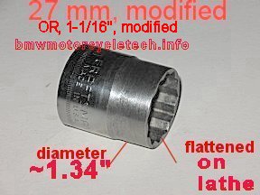
Regarding the modified 27 mm or 1-1/16" socket (photo, below):
Obtain a standard 12 point socket, not a 6 point. 3/8" or 1/2" drive, to match your existing torque wrench (or, get an adapter 3/8" <-> 1/2"). Square off the large working end of the socket until all of the small amount of inside taper is gone. You can do this best by chucking the socket in a lathe; but can be done if very careful about flatness and squareness, using a grinding wheel or flat sander. The lathe does the very best job, and it really is worth having this done properly if you do not have a lathe. This first modification of the socket is just to eliminate the taper in the working inside end of the socket. The socket needs one more modification. Remove one of the plastic caps over any one swing arm adjustment area. Take a careful look at the inside diameter(s) of the swing arm nut/adjuster cavity. You will probably see two diameters. These very with how the factory assembled your frame. Turn the outside of the socket on a lathe, or by hand on a grinder (a bit of crudeness is OK for this), so that the socket will fit very easily through both diameters in the swing arm cavity ...and the newly 'made square' end of the socket fits fully and quite squarely over the thin 27 mm nut. Do not turn/grind the socket too much, nor too little. Too much and the socket is weakened (another reason for a 12 point, not 6 point), too little and the socket will not pass easily by both of the internal swing arm cavity diameters, particularly on some bikes. Sometimes BMW did machine those two diameters concentric and very nearly the same size. It is very important that the socket fit squarely and solidly on the thin 27 mm locking nut. See near end of this article on how to adjust the swing arm if you want to skip to there, now.
1. There are two articles, besides my https://bmwmotorcycletech.info/clutch.htm article on this website, that you might want to read, and use the information in those articles as an adjunct to this article. Those articles are located at: https://airheads.org. Read the articles on the throwout bearing by Matt Parkhouse; and mine, on Lubing the Transmission/Clutch Splines. Those articles may prove useful to you. Reading those two articles may give you somewhat different perspective on the article you are presently reading.
2. Remove the gas tank. Engage 5th gear on the transmission (4th on a /5 with 4 speed transmission) and leave it engaged.
3. Remove the clutch actuating arm at the rear of the transmission. There were several styles of these arms. If you have a /5, you have a cotter pin to the boss; no problems with that design. The early style arm also has a grease fitting, and the throwout parts are different.
A bit later came a type used for some years and it uses a steel pin that has a circular groove, with a C-clip, and that clip is located at the lower area of the inside between the transmission ears. If you have this C-clip type I highly recommend you do a modification, a very simple job. See my https://bmwmotorcycletech.info/clutch.htm article. If you fail to do this modification, and the clip falls out and the pin comes partially out (it might also disappear) ...then the very next actuation of the bars lever will break off one of the two transmission ears, stranding you. The much later style arm uses a 10 mm bolt with waverly locking washers, and no troublesome C-clip. Hint: Insert the bolt so its nut is at the lower area. Yes, that is a bit of extra insurance. I prefer a Nyloc type of nut. The later arm has no grease fitting, last version had needle bearings. Some have modified the Airhead arms ...& the K-bike arms ...for grease passageways and a zerk. I consider that to be of much more value for the K bike.4. If the arm is of the late style, push through its steel sleeve (if you can easily) and in any event do clean the arm bearing and lubricate it with oil. I coat the outer faces (where the arm rubs the transmission ears) lightly with moly grease. It is quite common to see arm needle bearings as having never been cleaned and oiled since new. I usually use a bit of heat on the arm and then soak the warmed arm needle bearing area in a mixture of a light solvent and thin oil, and try to get the needles to be movable. Do not use a moly grease.
Remove the throw-out bearing by removing the rubber bellows cup (remove the strap clamp) and pulling the bearing assembly out. Inspect it carefully. Do not try to remove the inner central rod that is forward of the throw-out bearing. The earliest style throw-out bearing had ball bearings. A later not-as-good style had a flat radial needle/roller bearing, and after 9/80 it is a ball bearing again ...maybe ....because ball bearing types have been seen on years they were not supposedly on. Don't bother trying to convert to another style. There are some variances in the outer spring, black rubber cup, and the single or two part piston, etc. There can be problems with the throwout bearing ... the clutch article goes into it in detail, particularly about a tolerance problem with the later ones. DO READ IT, DO NOT PUT OFF READING about the problems with the sticky piston when hot!: https://bmwmotorcycletech.info/clutch.htm. If you have cleaned the throwout bearing it is a very good idea to lubricate it with a very light (low viscosity) smooth, non-fibrous, non-moly grease, before reinstalling it, as the throwout bearing does not get gearbox oil lubrication for some time/miles after you reinstall it.
Set aside the now cleaned and lubricated clutch arm and throwout parts. If not planning on removing the transmission, just pulling it backwards, it is much easier to move the transmission far enough to the rear for input splines greasing, with the clutch lever removed. In fact, without the lever removed, you probably can not gain proper access. Do not injure the transmission ears in any of your work! Keep filth away from the parts you just cleaned and lubricated.
5. Remove the air filter and all of the airbox. If you have the older clamshell type housing you will have to push the breather hose out of the half. If you have the later rectangular housing, and depending on what is in the area (pulse air parts, breather hose setup, vacuum line setup, etc.), you may have to move the breather hose forward. Replacing that breather hose can be a bit of fun, and it is easier at that time, to simply remove the starter motor cover. I recommend disconnecting the battery, before removing the starter cover (to avoid sparks) ...and you could do that now. With the starter cover off, it is a good time to check the tightness of the nuts on the electrical posts of the starter and solenoid switch. Inspect the condition of the breather system hoses. If you've have had oil breather problems, now is a great time to fix whatever is wrong. On late model Airheads, you can inspect the solenoid valves and the vent hose into the crankcase and decide whether or not to modify these things. You may want to change an early model disc breather to the later reed type & clear the bottom of the cavity small drain hole in the breather area (no drain hole on models prior to ~1978). There is nothing wrong with using the original early disc-type breather if in good condition; you could even make a replacement for the disc if poor ...and a few folks are making them for sale (see my references article: https://bmwmotorcycletech.info/references.htm.
https://bmwmotorcycletech.info/oilsketch.htm has all the breather information, well down that page.
6. Remove what vacuum, fuel solenoid and vent solenoid & smog parts, if any, that you have & need to or want to, on your particular bike (you may want to modify at this time or before re-assembly). You may want to read this article:
https://bmwmotorcycletech.info/pulseair.htm
Remove the left lower bolt on the transmission & the right lower bolt. Note the brown grounding wire at the left lower bolt if you have that. Pay attention to washers. Remove the upper bolts.
HINT: Consider the right upper bolt or stud, depending on what you find. Think about how much easier it might be in removing the transmission, if it was a bolt, and not a stud. It is easy to change! HINT: The 5 speed transmissions have a vulnerable neutral switch on the bottom, be careful!
If you decide to remove the transmission from the motorcycle:
Unfasten the driveshaft U-joint from the transmission (holding the rear brake strongly will help), remove the swing arm adjusters. This is where you use that modified 27 mm or modified 1-1/16" socket on the thin nuts. This is a good time to inspect the 4 special bolts that hold the U-joint...they must be the correct later shorter length
NO lockwashers! Loctite blue may have been used on the threads. If reusing the bolts, inspect them carefully.
If you have the rectangular airbox, remove the 13 mm hex headed bolt that goes straight down through the top middle of the airbox into the transmission. Removing that 13 mm headed bolt isn't needed on the clamshell airboxes. If you removed the bolt, then when you Reinstall that bolt later, coat the first few threads and the washer witha non-hardening thread sealant, such as Permatex Form-A-Gasket #2. Do not use the hardening (#1) version. If that bolt is loose, or leaks, oil will be sucked out of the transmission. If you have the rectangular airbox, you should now be able to remove the base box.
BMW uses metric size vacuum and fuel crossover hoses. Use of SAE (American, inch size) hose will make for more difficult fitment. I recommend the new type NON-fabric-covered BMW black hose. If you have a classic bike & want to keep it original-looking, you can get silver-cloth braded fuel hose from Bing Agency or VW dealerships, or some Independent BMW repair shops. I don't think it lasts as long as the later black BMW metric fuel hose. The longest lasting and the best hose I've tested so far is a special clear or faintly greenish plastic type, see item 11 in: https://bmwmotorcycletech.info/fuelmiscl.htm.
7. Some folks have a hard time removing and replacing the plastic input tubes to the carburetors. On some few models, these tubes are not the same, left to right, and may not be the same end for end, and only one fits the proper left or right side, and only one end of that fits the airbox and carburetor. Mark yours and their ends before removing! (such as: "left, to carb"; or, "right, to carb"). For the rectangular airboxes, and to some minor extent the clamshell type, for the purposes of this article where you are removing the airbox, it is easiest to leave these plastic tubes attached to the airbox half or base, and to loosen the clamp(s) at the carburetor end of them and when the the airbox is removed (especially, the rectangular box), the whole assembly lifts off easily, and replaces easier. If those plastic tubes are off and the rectangular box is already installed ...try re-fitting the carbs and intake hoses and plastic tubes all as one assembly at one time as you re-assemble the bike. If the airbox is in-place, and you are just R/R the carburetor, loosen the band clamps on the head side of the carburetor, and the ones on the input side of the carburetor, and then angle-out the carburetor and air tubes. Same, in reverse, for reinstalling.
8. Using the modified Chinese jack from my article, https://bmwmotorcycletech.info/hydraulicjack.htm, or by some other means, typically at the rear lower frame crossover tube (not as easy for a model with the pre-muffler under the transmission area); jack the rear tire barely off the ground. If you have a ride-off stand you may want to find a way to put a 3/4 inch or so piece of plywood under the ride-off stand by rocking the stand left/right, as you install a board. Bikes vary, play with yours until you find out what is needed. Remove the plastic covers over the swing arm adjusters, and loosen the two 27 mm nuts with the socket you modified, only 1/4-1/2 turn loosening is needed, and then unscrew the allen-center adjuster on each side, and remove those adjuster-pin with the nut still attached; being careful to not damage the pins threads.....You have to wiggle the tire/swing arm a bit to allow the adjusters to be removed, & that helps avoid damaging the adjustor-pin threads.
I have seen bearings not lubricated properly & badly rusted, & cracked! If yours are bad, or really need a full clean & lube, then I recommend you remove the entire rear end of the bike & service the swing arm bearing area. Various pullers are available to remove the outer bearing race. Ed Korn (see https://bmwmotorcycletech.info/tools.htm article) made a cute one in a kit to also install the new one. It is a simple job. The swing arm bearing is basically the same as the pre-1985 wheel bearing, a common type from any bearing supply company. I prefer to not use sealed versions of those bearings (or, I remove the seal), allowing me to better grease from the outside now and then, after the bike is reassembled, via the center Allen wrench hole in the threaded pin adjustor, using my greasing tool with the rubber tip.9. There is sometimes no need to undo any shift linkage for just a basic spline re-lubrication. You do have to undo the wing-nut on the rear brake rod, if you have a rear drum brake.
10. Pull rearward on the transmission. It will likely come backwards a bit. The limit for the rear movement is typically not the clutch ears but the driveshaft housing interfering with the frame cross tube. You will probably find you need to hold the transmission backwards. While you can use some pieces of wood (not metal) to wedge into the transmission-engine opening (and may end up doing that anyway), you may want to fashion some means to keep the suspension/etc moved to the rear. I do this by hooking a strong bungee from a lower spring/shock unit, back to the turn signal tube or rear rack, quite tightly (on both sides if a twin shock model). If you play with the transmission and rear end movement a bit, you will find that you can separate the transmission from the engine enough so the input shaft forward end is visible. You can also use the method in the next paragraph.
Some of the old BMW Factory Service Manuals did call out using a piece of wood to keep the rear end moved rearwards. In fact, they specified it when removing the transmission. I do not mean using a piece of wood between transmission and engine; which is not absolutely necessary, certainly not with this BMW-suggested piece of wood. In my only BMW manual that specifies the size, BMW said to use a 20 x 400 mm piece of wood, placed between the tire and the rear section of the frame. This does work, but you will almost certainly have to find out what the wood wedging piece thickness will need to be for YOUR bike, as it is not the same for all years and models, and, of course, tire sizes.
It is not uncommon for someone to complain that the transmission will not move backwards much. See #9, above! Rear brake tight? ...if so, undo the wing nut.
If you see an oily spline at the transmission & see oil coming from the input end of the transmission, you must undo the universal joint, remove the transmission entirely, & replace the transmission input seal. Failure to do so will result in eventually oiling the clutch. This is an easy job if the transmission is out, you do not have to take the transmission apart.
11. Blow out any dust and dirt from the area. Do that now, rather than later. DO NOT breathe-in that dust. Under NO circumstances do any prying with metal tools that will nick the transmission-engine mating surfaces, thereby causing the transmission not to re-assemble dead squarely to the engine. Clean the splines of the INPUT shaft (NOT clutch disc!)....but...if the splined center of the clutch disc is very greasy, clean with a rag the OD and ID. DO NOT SPRAY SOLVENT ON THE DISC SPLINES.
To both clean and grease the transmission shaft input splines when the transmission is still in the motorcycle, I made up TWO simple tools:
Use two common "acid brushes". These are small brushes built into the end of a tubular piece of thin sheet metal. You can get them at most hardware stores, or Harbor Freight has quantities of them quite cheaply. Cut the bristles down in length, by maybe nearly 1/2, so the bristles are stiffer. Tape or otherwise securely tie each brush to some sort of thin rod or any similar items, such that the brush handle length is extended. One brush tool can be your permanent tool for cleaning the input splines, the other is for your permanent tool for greasing those splines. You only need make these two tools once, so after you are done with them, clean them and put them on your shelf of BMW tools. I use wood dowels from the hardware store to which I attach the brushes with tape. I am guessing my wood dowels are maybe 3/8" in diameter.
To clean the transmission input splines, use some sort of medium-strong petroleum-based solvent on one of the brushes; move the brush back & forth on the TRANSMISSION INPUT SPLINE. I brush FROM the transmission TO the forward end of the spline. Rotate the spline as need be by rotating the rear wheel. I like to finish the splines cleaning by spraying a good cleaner on them while rotating the rear wheel; but, remember, do NOT spray clean the spline of the disc! For the disc, you can poke & wipe with tiny rag pieces if need be (You CAN use a SMALL AMOUNT of solvent on those tiny rag pieces). I find long curved forceps good for this. If you spray solvent into the clutch disc splines (don't!), ...that can put grease/oil/grunge, into the friction disc ....so do NOT do that. Common spray BRAKE CLEANER does NOT do a good job for cleaning; in fact it is LOUSY. I use acetone, MEK, or similar strong and fast evaporating solvents. I also have used Berryman B12 Carburetor and Choke Cleaner in its spray can, with its spray wand, ON TRANSMISSION SPLINES.....I try to avoid getting it on the seal.
If the transmission input seal and splines area shows OIL leakage from the transmission, remove the transmission and replace that input seal ...and ask on the Airheads LIST or check my article on how to replace the seal: https://bmwmotorcycletech.info/transmission.htm. It is not difficult & you do not need to disassemble the transmission. Failure to replace a leaky seal will eventually ruin your clutch. There are two ways transmission oil can get into your clutch. One is via a bad transmission input shaft seal. The other way is a missing round tubular FELT. It is hidden, and located around the pushrod that passes from the rear throwout bearing area to the tip of the input shaft, on all early models. It is easier to install the felt from the forward nose (input shaft spline end). If you have NOT removed the transmission, you have likely not been able to remove that rod accidentally, so, you should have no problem with that felt at this point, as the felts last darn near forever. Later models do not have a felt, but a seal, located inside the rear of the transmission, and that seal is NOT simple to replace, and the pushrod is differently installed.
Grease the INPUT SHAFT splines once the solvent is totally evaporated. Work the moly grease into the splines, bit by bit, all around, rotating the splined shaft by means of the rear wheel. Grease the splines using your greasing brush tool. It is not needed, nor desirable, for too much grease. Moly greases work best, see my article on chemicals, etc.: https://bmwmotorcycletech.info/chemicalsetc.htm
Ideally, the transmission, when in the bike, is backwards far enough to see the end of the input shaft. If so, then use a long screwdriver (or?) to move the pushrod towards the rear just enough to get to the pushrod tip. Do this as the splines lubrication last step. If the rod end that is in the center of the input shaft is not visible, make it just visible. This is usually easy with the clutch lever having been already removed at the rear, just a slight push on the rear of the rod. Put ONE SMALL drop of your moly grease on the rod tip. I suggest you also put a drop at the rear end of the rod where the clutch lever operates.
Clean the surfaces of the transmission case shell that will contact the engine surfaces. Take your time to do this properly. Under NO circumstances are any nicks, nor filth allowable, that would keep the transmission from SQUARELY & FULLY mating to the engine surface. Clean both engine mounting surface and transmission mounting surface. Keep in mind that a prior owner or workman could have left nicks which could keep the surfaces from mating 100.000%. Fix any such things. Since YOU did not use metal tools in prying the transmission-engine apart, YOU did not leave nicks. Correct?
12A. Reassemble everything, bit by bit, slowly, and carefully. This is the last moment to change the upper right engine case fitting, so decide now if you want a stud or a bolt. If you decide to install a bolt, use a small amount of antiseize compound on the bolt threads.
INSTALL THE TRANSMISSION. Do NOT allow foreign matter to interfere with the transmission coming up to the engine cleanly, squarely, fully. Be sure the transmission is fitting squarely. If the transmission input spline will not engage the clutch disc, then rotate the transmission output flange slightly (or rear wheel slightly if transmission flange is still bolted-up). Cinch up the bolts, evenly, in a cross pattern.
Do not forget the vertical 13 mm bolt (you HAVE used a soft non-hardening sealant on the bolt threads, under the bolt head and both sides of the washer?). The clam shell model requires the right-side clam shell to be in place for this. Do NOT forget the grounding wire at the left lower bolt.
HINT! Clutch cables can last a very long time, but some break prematurely. In my experience there are a number of possible causes for broken cables. Sometimes from being poorly made at the handlebars end (yes, BMW has had some bad cables); sometimes from owners using more than the one-only zip tie; sometimes from unknowledgeable owners lubricating the genuine BMW cables (DO NOT LUBE), ETC. While information is in my clutch article about making sure the barrel and cable fits and rotates correctly at the handlebar clutch lever; NOW is the perfect time to be sure the lower end of the clutch cable (the barrel) fits properly in the transmission-located clutch arm, since the arm is still removed. I have found the majority of transmission-located clutch arms do not fit perfectly for lower barrel rotation. At the end of the lever is the 1/2-moon place the barrel fits. The check and fix is very simple. Using a dowel or whatever round tool is of appropriate diameter that you have (I usually use a fine rattail file, then fine sandpaper), carefully enlarge the half-moon area of the lever, so that the barrel of your cable fits very smoothly, and can be rotated smoothly.
You can now reinstall the throwout parts & the clutch lever at the rear of the transmission. Do any cleaning and lubrication there that you did not do previously. This includes moly grease at the barrel of the cable and slight amount on sides of the lever where it fits to the transmission and a dab of the grease onto the rear of the pushrod.
Check for proper cable adjustment, see clutch article! https://bmwmotorcycletech.info/clutch.htm
12B. Centralizing & adjusting the rear swing arm:
After the adjusters and locknuts are reinstalled into the frame cavities & engaging the swing arm, the allen wrench opening adjusters (pivot pins) need to be adjusted. If you did not move their locknuts originally except perhaps 1/2 turn, or 1 turn, as needed to just loosen them, it will be a bit quicker. What you must do is screw both adjusters inward with an Allen wrench, as evenly as you can on each side. View the space between swing arm and frame, to eye-ball the 'even-ness'. DO NOT tighten them much, moderate finger tightness is all that is needed and desired at this point. Try to keep the swing arm roughly centered in the frame. You can use a selected small allen wrench from the BMW on-bike tool kit, or a selected diameter of drill shank as a thickness gauge, placed between the FRAME and the SWING ARM, to measure the centering of the swing arm in the frame. This may take a few attempts until the swing arm is centered; that is, the selected size of drill shank or allen wrench inserted between frame and swing arm shows the same spacing, side to side.
Loosen one pivot bolt, tighten a wee bit the other. When equal, use your torque wrench with a Allen adaptor of 6 mm size, the other end�matches your torque wrench square size. You want 7-1/2 footpounds of torque on the adjusters AT THIS POINT OF THE PROCEDURE (the 27 mm nuts must not be tight). Recheck that the swing arm is still centered, with 7-1/2 footpounds. Assuming that you now have equalization of spacing, torque ONE of these pivot adjusters to 15 footpounds. Then, back off a bit, and re-torque to 7-1/2 foot pounds, stopping at 7-1/2 whilst going only in the clockwise tightening direction. If the spacing is now still fairly equal, fine, if not, back off one adjuster, tighten the other, in the same manner, & repeat until near perfect.
In BOTH INSTANCES, the pins are to be tightened to 15, then backed off and retightened in CW direction to 7-1/2. When you are done, the spacing of the swing arm in the frame should be equal on both sides. Lastly, tighten the 27 mm thin steel nuts with your modified socket & torque wrench to 70 to 75 foot pounds. Some folks paint-mark the end of adjusters-to-nut (pins) to be sure that they have not moved while the 27 mm nut is being tightened, usually the pins do not move. There is nothing super-critical about equal spacing. There is no official specification. If you are within 0.010" to .020", that is quite good enough, in my opinion. The original purpose of the 15ftlbs, then 7-1/2ftlbs, was so if the bearings were freshly greased, then the 15 made sure the grease was squeezed to proper thickness. You don't want to leave the pins at 15, because that does warp the frame/swingarm; ...hence use the 7-1/2 factory specification as the final adjustment. The 15 and the 7-1/2 torquing feeling is not dead solid, but feels like something is giving a bit, and, it is. Once you have done this procedure, the long form of which I have shown, above, the next time will be much quicker.
NOTE! ....To be sure there is no confusion here; there will be NO feelable side to side freeplay in the swing arm to frame mounting when you have adjusted the pivot adjusters properly. You are taking up all free play, equally spacing the swing arm in the frame (side to side), & then leaving the adjustors (pins) with some torque on them, specified at 7-1/2 footpounds, AFTER first torquing to 15 footpounds, backing off, & resetting to 7-1/2 footpounds IN THE TIGHTENING DIRECTION. Obviously, setting one side presses the swing arm towards the other side, so you can't do both at the same time together. You do the centering adjustment, bring the pivot adjusters close to correctness & then adjust ONE side for proper torque & see if the other side & the first side match in spacing. Use your torque wrench with the Allen adaptor of 6 mm size, the other end the square drive to match your torque wrench. You do NOT have to unscrew the pivot pin in order to grease the bearings; see next paragraph.
NOTE! ...I grease my swing arm pivot/bearings roughly twice a year, depending on my traveling conditions and mileage. If you get into deep water very often, you may want to grease much more often. I grease both sides pins with my pointy-tipped grease gun with the tapered rubber tip (common item, NAPA stores or chainsaw stores for the grease gun part). Every few years I pull the entire rear structure backwards enough to hand-clean & eyeball inspect & finger-feel the condition of the swingarm bearings.
When greasing, through the allen hole with my rubber-tipped grease gun, I use a quite goodly amount of grease, which forces out old dirty grease. I then use my fingertip to wipe the excess grease, all-around, to smooth coverage at the junction of swing arm and frame. Making this clear, the grease is left, that spacing area is full of grease, but smoothed, in the area between the frame inside surface & the swing arm inside surface. That way, any water getting in the area will see a layer of grease in that area for which you set the equality distance. I prefer the NON-sealed bearings, so all this greasing works properly. If I have a sealed bearing I am installing, I may, on purpose, destroy/remove the seal first. Late models may have sealed swing swing arm bearings ....I have seen earlier models with this type. With an intact seal you have to go about greasing things differently, usually you must a sharp grease needle from the side, through the seal, etc. I prefer UNsealed bearings, with a lot of grease, smoothly done in the mentioned space. I mentioned the early style seal used with the standard open bearings earlier in this article and see the next paragraph. If you want to use sealed bearings, that is OK, but up to YOU. The bearing is the same type and size as used on the pre-1985 wheel bearings ....type 30203, a very common part, available with and without seals.
Re-greasing using your rubber-tipped grease gun every year, through the allen pin, will insure you have forced contaminated grease out of the bearing, at least fairly well, and the bearing should last a long time.
The R45/R65 models came without one spacer & grease containment inner plate item.
NOTE: There are two places on the Airheads where the bearings are hardly moved much, and certainly not rotated round & round, as do wheel bearings. One place is the needle bearing in the later version of the clutch lever at the rear of the transmission. This article you are reading says to clean it so it, oiled, rotates OK. No grease, just oil. Another place is the swing arm bearings under discussion above. Another place, with a bit more movement, but still not all-around, is the steering head bearings. While you CAN use the soft red or other type of wheel bearing greases I've described in this site, those are NOT as protective for short bearing movements as using a low % soft moly-added grease for them. For my own bikes I sometimes use a soft grease, and mix in a small amount of moly grease. I have plenty of moly lubricants left from projects, and may use wee amounts of such as Staburags, etc., ...it works well for these two places. You can use, for the bulk of the grease, any common smooth non-fibrous grease, even BMW's red grease, or Chevon Ultra Duty, etc....adding a wee bit of moly is up to you. DO NOT use a high % moly.
NEVER use a moly grease for wheel bearings.
13. Clutch Adjustment: https://bmwmotorcycletech.info/clutch.htm
Revisions: � Copyright 2020, R. Fleischer
Return to Technical Articles LIST Page
Return to HomePage
Last check/edit:
Wednesday, August 16, 2023
01-15-2003: Clarify & add to tools list; add applicability & skill level; add reference note on 50,45, 40 mm bolts.
01-22-2003: Add section on adjusting the swing arm and clarify details. Add hyperlink within the page for that adjustment. Add #13.
04-16-2003: Add .htm title; clarify many details.
05/06/2003: Add note on ball type throwout bearing seen on 1984; note to coat the 13 mm bolt's WASHER in top of transmission; typos; input seal note in #10; clarifications.
05/11/2003: Rework #12, to eliminate one reported incident of someone managing to jam something or other. How???
05/15/2003: Correct typo, 1-1/6" should be 1-1/16".
07/26/2003: Expand #13, add ref to #3, and add #14.
08/28/2003: Add #15.
11/21/2004: Remove #15, back into #13, and references to #3 added as necessary.
06/01/2005: Bearing number added.
07/10/2005: Updated to eliminate some confusion in procedure.
07/11/2005: Additional small changes on adjusting swing arm, and about the seals there.
07/23/2007: Some editing for clarity.
11/04/2008: In item 13, change part number of pin from 23-21-1-241-484 to proper 23-13-1-241-484.
12/05/2008: Update item 12 for clarity.
08/31/2009: Minor clarifications.
10/27/2009: Clarify a lot more details.
10/28/2009: Add wing-nut information, #9, #10.
06/24/2010: Add information on why fine & not coarse splines at the input shaft, clean up article a bit (not a thorough job).
07/02/2010: Corrected minor typos, clean up article, add notations to clarify about K bikes, other minor stuff.
05/16/2011: Fix typo in #12.
10/13/2011: Minor for clarity.
10/19/2011: Do a bit more re-arranging, etc., for clarity.
11/16/2011: Removed discussion on specific greases, and refer to my extensive article #73.
04/08/2012: Clarify details on throw-out bearings, and a few more minor points elsewhere's.
06/08/2012: Completely re-write #14, and add note at top recommending reading the Clutch.htm article
06/28/2012: Re-do clutch adjustment section to agree with the just updated similar section in CLUTCH.HTM
10/06/2012: Add QR code; add language button; update Google Ad-sense code; fix some typos, clarify a few details. Language button removed in 2013, due to javascript problems.
04/28/2013: Shorten article by using references to Clutch article. Clarify more details, clean up, etc.
09/22/2014: Minor cleanup, nothing of importance technically. A bit more on 08/22/2015 and 8/24 (hints).
11/29/2015: Finish cleanup and meta code changes. Add note about the seal rings. Adjust spacing so most of article is to left side.
03/05/2016: Update meta-codes, layout, fonts
08/05/2016: Update metacodes, scripts, H.L., layout, clarifications, remove some redundancies & unneeded comments, etc.
11/19/2017: Fix typo at 12A, was left, should be right.
02/02/2018: Go through entire article. Reduce excessive html, fonts, colors. Better explanations.