
|
|
How Spark Ignition Systems work
...vastly more than you wanted to know....
This is article ALSO contains, revised, the deleted from being separate old article 'IgnitionSystems'.
�
Copyright 2020, R. Fleischer
https://bmwmotorcycletech.info/ignitiontheory.htm
28
PURPOSE, details, etc:
The purpose of a spark ignition system is usually spoken about as simply to provide a hot electric spark at a spark plug electrode gap located inside the combustion chamber. This spark is controlled (timed), to occur in the correct relationship to piston travel ....and as needed for rpm changes. On some vehicles, but not on BMW Airheads, ...control is also in relation to throttle position or intake manifold vacuum or pressure,or both.
While the electric spark itself is usually thought of as simply igniting the fuel-air mixture in the combustion chamber by the heat of the spark; this is not correct. It is the ionization function of the PRE-spark, just before the spark actually occurs but the spark voltage has been applied. Once the voltage exceeds the dielectric strength of the spark plug gap, the now ionized gas becomes a conductor and allows current to flow across the gap. This ionization idea can be quite nerdy to discuss, and you can probably safely forget I mentioned it!
There are now ignition systems developed by such as Delco that use the ionization principle specifically to provide an electrical signal, that, applied to the ignition electronics, allows some improvement in ignition quality and thereby possibly increases fuel mileage. While I do get into the ionization idea a wee bit more later in the article you are reading ...besides a lot more both simple and technical things, ...I do have an article that discusses this somewhat esoteric development ...see item #19, here: https://bmwmotorcycletech.info/nerdy-stuff.htm.
In the stock BMW Airhead motorcycle ignition system, there is one spark plug per cylinder; both cylinders have an ignition spark at the same time, but only one cylinder is under compression pressure, so the other cylinder is said to have a 'wasted spark'. Both two ignition coils and one dual-tower type coil systems have been used on Airheads by BMW.
The higher the pressure in the combustion chamber, the more spark energy is needed to jump the spark plug electrode gap. If the mixture of fuel and air is quite lean, the ignition can be marginal unless quite powerful. Lean mixtures offer better fuel mileage, if not excessively lean.
If you were to try to test for a possibly faulty ignition coil, the standard test via looking at the spark in the normal gap of a spark plug located outside of the cylinder is marginal, it only shows a spark or not, and maybe a bit about its strength or weakness, if you are experienced at looking at the spark. This is not a very good test ...you need a much wider gap to see if the coil is capable; or, a type of apparatus that puts a spark plug into a pressurized (typically from the shop air compressor) container ...and has a high pressure safety window to look through. This type of apparatus tests spark plugs & an advanced type also tests coils. It is called a Bomb Tester. I don't know the history of why those two words were used. It is also not a perfect test. Information in more depth, especially on antique methods that BMW suggested for testing spark gap tests, is in my other ignition articles.
It takes less voltage to jump sharp pointed metal parts, and the less gas/air pressure around the gap the less voltage required. For coil testing, I keep a few old (but cleaned) spark plugs for external-to-the-cylinder tests, with the ground electrode almost totally removed, and thus the gap is quite wide and is more revealing about spark quality.
The rest of this article, which is quite long, contains both simplified and complex explanations. You will know vastly more than most when you have finished reading this article!
This article purposely, in a few areas, explains certain things in more than one way. Experience has shown me that doing this is needed to get full understanding by some folks, and I really do want everyone reading this to understand everything; maybe even the nerdy sections. I put the nerdy sections into this article in scattered areas, to try to avoid overloading your brains.
The earliest ignition systems that had much similarity to todays' were in the days of quite early automobiles. At around the same time that magneto's were in use (rotating magnets inside of coils with thousands of turns), there were also wooden boxes containing some iron metal rods or other iron shapes, with turns of wire wrapped on them in two windings, one with a very large number of turns, the other with far fewer turns. Spring loaded electrical contacts were arranged such that a storage battery fed electricity into the lesser-turns coil of wire wound on the iron core. That caused magnetism to be developed in the core. One end of the iron core was in close proximity to a thin metal reed to which two contact points were affixed. The magnetism, when great enough, pulled the reed away from its normally closed position, usually to a second contact point (or, no second contact), interrupting the current flow. This repeated over and over, rather fast. The "vibrating contacts" opened and closed, similar to a very old fashioned electric vibrating door bell (and, many vehicle horns). Since the vibrating contact opened and closed the circuit rapidly, the low-turns coil winding (called the PRIMARY winding) was interrupted from current flow quickly and often. Each time the contact closed, the coil charged up magnetically, and each time the contact opened, the coil transformed that stored energy into high voltage in the SECONDARY winding by a process called transformer action. Those many extra turns on the secondary winding 'transformed' the low voltage of the battery to a few thousand volts, and this was applied to a spark plug. In many, if not most very early cars, that high voltage was applied continuously to a spark plug. Thus the spark was essentially continuous at that spark plug. This was so since the supplying contacts were vibrating. This was usually only done on one or two cylinder engines for automobiles, although seen on some 4 cylinder antique engines. Farmer's engines usually had magnetos, so did not need batteries.
Engines with more more than one cylinder usually had a circularly rotating switch called a distributor, usually mechanically driven from the engine camshaft, that selected the particular cylinder's spark plug to be energized. There were some early engines that had one vibrating contact coil per cylinder; and even some that had a very large diameter rotating magnet magneto that had individual coils for each cylinder.
One advantage of the battery and vibrating contact system was that the engine did not have to be manually rotated strongly during starting in order to have a decent spark. The earliest gasoline powered cars did not typically have batteries, nor electric starters; instead, typically some form of magneto (using a permanent magnet) was used.
The problems with the vibrating contact system were:
1. A battery was required.
2. The high voltage output is relatively constantly flowing, compared to ignition speed, & it is hard to 'time' the initialization of the combustion event, even if one had the rotating contact distributor. This was not a big problem with the only available engines which were very low horsepower, using very low compression-ratio engines, with very low rpm. Even today, a typical vibrating contact wooden box coil of the type described is still easily purchased brand-new; for Ford Model T cars or your own fun and games.
3. The battery current input had to be kept low in order to keep the points from deteriorating rapidly.
Later systems used one or two breaker points sets, typically located within the distributor, with a capacitor ("condenser") to reduce points wear and 'condition' the electrical waveform to better work with what was universally now called the Ignition Coil. No vibrating contacts were used. The points are mechanically driven by the engine camshaft and are adjustable for gap and for ignition timing, thus the spark can be made to occur at a precise position of the engine piston(s). This system is generally called a Kettering Ignition, and is capable of high performance, and is still in wide use today, the points having been finally eliminated in favor of electronics. The distributor is still in use, but many modern vehicles use individual coils or shared coils for the cylinders, and no longer use rotating distributors. That reduces maintenance and increases reliability and preciseness, and I expect the use of distributors to disappear, which lowers vehicle cost....and, allows/demands the use of electronics to control the output timing and other characteristics. Fuel mileage can thereby also be increased.
"Condenser"; when used for electricity, is an old name for an electrical item called a capacitor. BMW Airhead motorcycles had points and condenser on all models up to and including 1980. Basic condensers consist of two very long pieces of super-thin aluminum foil, and a means of insulating these two pieces of aluminum foil from each other, and the long pieces and insulation are all wound together at the same time into a tubular shape; with one connection to one piece of foil, one connection to the other piece. A capacitor, or condenser, has the ability to store an electrical charge directly. A battery does not, in case you were wondering about that ...a battery stores possible electrical energy as a possible chemical reaction; and when the battery is called upon to deliver electricity, then the chemical reaction begins. The condenser (capacitor) stores excess electrons on one of the long strip pieces of aluminum with regards to the other piece.
A capacitor (condenser) takes time to fully charge from any applied voltage, and the faster it is charged, the more current flows into the condenser during that period of charging time. There are two primary purposes for the capacitor in the points-type ignition system. (1) It greatly improves the quality of the spark and charging/discharging waveform, by making sure that nearly every bit of the energy stored in the coil is used ...to transform ...the primary coil magnetic energy ....to the secondary high voltage winding ...just how it does this is more than a little complicated; (2) the capacitor greatly reduces the erosion of the points by dampening the spark that occurs at the points as they open.
When the points close, power from the the battery travels through the coil(s) primary winding(s), through the points, to ground (ground means the other terminal of the battery, same as the engine metal, to which it is connected). The flow of electricity causes a substantial magnetic field after a very short period of 'charging time' ....in the ignition coil metal core and winding. The points cam shape insures that the charging time (points closed time) is typically much longer than the points opening time, for any RPM.
As the camshaft rotates, at the very instant the points start to open, the charging circuit is opened, and the coil(s) magnetic field collapses, made more speedy and in a way more powerful (it makes some of the DC act like AC) by the condenser, which is often wrongly thought of as just something to help reduce the electrical arcing at the points. All the time the points are closed, the condenser, which is electrically wired in parallel with the points, is fully shorted, which means fully discharged. When the points open, the condenser, for a very brief moment in time, still looks like a short circuit electrically, since there is no electrical charge on it yet. The coil primary circuit does not have current from the battery anymore as the points are 'open'. The magnetic field collapses, a reverse current flow charges the condenser as much as it can during the short period of time (the time also being a function of electric specifications of the coil and condenser, etc), and the current flow reverses or call it oscillates, that is, the constantly varying electron flow is going +, then -, then + ....all the while the magnetic field is first, quickly, inducing a large voltage of less current into the secondary coil winding. The electricity is ping-ponging, perhaps you want to think of it like a ring of a bell. Electronics engineers think of the circuit as Low-Q, Series Resonance. Now, does THAT make you feel educated more? I will discuss this RINGING, or oscillatory waveform, just a bit more, because understanding it is the key to understanding the Kettering ignition.
The actual waveform of the electricity is a type called a damped waveform, or you can just consider it a sort-of-sine wave that is constantly getting smaller. This all becomes extremely complex when the spark occurs, and I do not want to get deeply into what happens, nor use terms such as resonant circuit, waveform analysis, rise-time, and so on. Suffice it to say, the points open, the magnetic field collapses, in turn inducing a high voltage in the secondary winding, which is applied to the spark plug. At this point the gas in the spark plug gap ionizes, the spark occurs, and the fuel-air mixture combusts, the gas pressure formed moves the piston inwards.
The condenser does, greatly, reduce sparking/arcing at the points, because when the magnetic field collapses in the coil, it causes that reverse-current, at substantial voltage, to be across the points as the points open, but the condenser absorbs much of it. The condenser takes a teeny bit of time to charge up some as the points are just barely opening, so the condenser acts like a short circuit, then less and less so as it is charging during that very short time period. You can also just think of this as the electrical charge direction in the coil reverses, and then tries to charge up the condenser in one direction, then the waveform reverses and the charging to the capacitor reverses its polarity, and occurs at a slightly lower intensity, which takes a teensy bit of time .....thousandths/millionths of a second. The condenser ensures that the coil secondary winding develops a very large voltage, of a waveform that is 'constantly decaying & oscillatory'. It is the large voltage that is applied to the spark plug. The spark jumps across the spark plug gap, and also eliminates a potential problem: If the spark plug wires were not connected to a spark plug, but just open/hanging, voltages in the coil WILL reach extremely high values, MANY tens of thousands of volts, and the coil windings insulation would likely be damaged. Do not be confused by statements in various literature about such as 40,000 volts, etc.....that is the ultimate voltage that may be reached in an ignition system without a secondary winding spark gap in operation. The actual voltage for ionization and spark is much lower.
This type of ignition: coil, condenser & points, is called a Kettering ignition. It, by a sort of trickery as outlined, lets a D.C. circuit act like a bastardized form of A.C., ....and the A.C. is 'transformed'. The ignition coil is the transformer, transforming the battery voltage to a possible 20,000 volts or more. The transformation, for the nerdy here, is a waveform that is a decaying oscillation type, usually portrayed in text books as a decaying amplitude sine-wave.
NOTE! The actual waveform, as would be shown on such as an oscilloscope, is more complicated than I am explaining. If you wish to learn the complete story, I suggest you use a Search Engine and have a very large cup of coffee available.
If you are thinking ahead some here, ...yes, the electronic ignition of the 1981 and later BMW Airhead ignitions are updated forms of the Kettering ignition. The points circuit of the 1979-1980 and also 1970-1978 Airheads is the same as what I have already described. For the electronic ignition of 1981 and later, the points are replaced by the Hall element, which triggers the module to turn on and off, which does almost exactly the same thing as the old Kettering ignition points. A condenser is not needed in the 1981 and later models.
The Kettering style of circuit is simple, reliable, and in our Airheads and K bikes, it is perfectly adequate for well over 7000 rpm, even though coil output drops with rpm increase and an increase in the number of cylinders. That is, the more sparks per second required, the less time for the magnetic field to charge up fully, causing less voltage to the spark plug...and less energy in the spark that does occur. The 2 cylinder Airheads do not need a more powerful ignition than that supplied originally.
The current and voltage at the points causes the points to deteriorate, slowly, over many miles. The best quality points have a thin precious metal or tough metal coating, such as tungsten, which helps with the erosion, but the coil, condenser, & points systems, are also not perfect. The points not only arc electrically, but that electrical arc tends to cause a type of wear that is called tit and valley (mountain & valley if being Politically Correct), so one side of the points has a tit, the other side a matching valley, and slightly irregular in shape and fit. When these get extreme enough, the points don't work all that well, and filing the points, even if carefully done, only lasts a moderate amount of miles ....but, in truth, can be done over and over ...for some longish miles usually. Timing needs to be checked too as the points and their rubbing-block wear. Generally speaking, points gap and timing checks need to be done every 5,000 miles, and at that same mileage the cam, and felt (felt piece is part of the points assemblies before 1979) needs some slight re-lubrication. The lubrication is to help ensure that the insulating rubbing block on the points does not wear fast from lack of the needed small amount of lubrication.
BMW's from the end of 1969 (/5 and later models), up through 1980, all had coil ignition with a points contacts assembly being driven off the camshaft. Points contacts are nothing more than a switch. There is a condenser, electrically connected across the points. This system of contact points, condenser, and coil (or two coils on some Airheads), all being driven by a battery, was invented by and still named for Mr. Kettering. It is a major improvement on the vibrating contacts coil method. Note that a magneto, with its condenser, is basically a simplified sort of Kettering system, although never thought of that way. There are two lobes on the cam called the points cam, that is at the forward end of the valves camshaft, whether located on the camshaft tip area in the ATU in pre-1979 models, or in a canister on 1979-1980 models. Each of the two lobes will open and close the points for a camshaft revolution (which is once every two crankshaft turns).
Amplifiers and Boosters (preliminary introduction):
As noted, points deterioration, and the tits and valley effect are wear areas. Another major wear area is the rubbing block. It needs to be faintly lubed, which is done via faintly greasing the associated cam, and, on the pre-1979 models, the felt. If not abused, the spring will hold up for the points assembly extended lifetime. One type of abuse is opening the points way too wide with your fingers.
A points amplifier, also called a points booster, is a transistorized circuit. The transistors (of whatever type), act as the power switch that handles the otherwise large amount of electric current, instead of the points. The amplifier/booster is designed so a small voltage and small current is applied to the points, and the points opening and closing triggers the booster's power transistor, which, as a switch, controls the coil(s) primary current from the battery. The circuit may have resistors, diodes, and more than one transistor, but all boosters/amplifiers have the same basic function, which, all parts inside them together, reduce the current and voltage at the points and act, over-all, as a power switch, that does not have such as points erosion, tits-valleys, etc. Thus, the points can last MUCH longer than they might otherwise without the amplifier/booster. It is important to continue checking points gap, timing, and for the slight lubrication of the points cam (and felt if present), at 5000 mile intervals. For the 1979-1980 canister points ignition, the same holds true, except that there is no felt.
The most popular amplifier/booster is ...I think ...the one from Dyna. There are other sources, and even kits to assemble your own. It is quite possible to use a modified kit to handle the higher currents demanded by low primary ohms coils. You will find the kits information, etc., near the top of: https://bmwmotorcycletech.info/Ignition.htm
Magnetos, Kettering, Diesels, CDI, Electronic triggering, ATU cam, Dwell, Amps, even some nerdy stuff.......etc:
Magnetos are a permanent-magnet method of using mechanical rotational energy, instead of a battery, to produce the high voltage for the spark plug. Magneto's are usually equipped with a set of points (contact points plate), and a condenser, and the energy transfer from the small number of turns coil in the contacts plate circuit primary circuit, to the secondary many turns winding, is done at the moment the points open, which is set to coincide with a particular high energy alignment of the iron core stator... in relationship to the rotating magnet (actually at the switching point of magnetic poles, but that is a nerdy point here). Magneto output rises with rpm (as opposed to coil ignition which has a reduction in output with higher rpm. Since the exact time the spark occurs can be controlled by positioning the points, same as with the points and coil ignitions, timing on magnetos can be precise-enough. Many early BMW motorcycles (before late 1969) used a magneto system. A big advantage is that no battery is needed. Magneto ignition has been, and still is, used in many motors, from lawn equipment and motorcycles to aircraft piston engines.
If the motorcycle had electric lights, some electrical source method is needed, either as part of the magneto system, or from an alternator or generator.......and usually, not always, together with a battery. It is not a necessity to have a battery as incandescent lamps can be run on alternating current from a specialized magneto or an alternator. This was even done with generators occasionally. Some versions of quite old but popular scooters (Vespa, for instance), had minimal lighting systems, run on A.C. from a separate coil in the magneto system. There are some modern dirt bikes that use A.C. for lighting.
Magneto's are difficult to keep down in size and weight when you need quite high energy sparks (such as with lean-running engines or engines with quite high compression ratios, or both). Magnetos have rotating mass with inertia which may be a factor for engine or camshaft design, since they are typically attached to the crankshaft or camshaft. Magneto's have some other problems, that is why they are not used much now on modern designs. Magnetos do have increasing voltage output as they rotate faster, but, for motorcycles, that means lower output when you are kick-starting the engine; and, if anything is slightly marginal, the engine may not start; or not easily. Some older race engines used them, but most race engines now use sophisticated electronic ignition. Magnetos, or some form of them, are still used in many small engines, especially in things like home garden and other equipment. Some small motorcycle and scooter engines still use them. Magnetos are also used with piston engines in aircraft ...most have two such magnetos, allowing firing of two plugs per cylinder, for safety redundancy and higher combustion efficiency. There are a few small utility engines that use stacks of ceramic discs, pressure driven by a cam, to produce ignition voltage. These ceramic discs are very special, and squeezing them tightly produces voltage.
There are other types of ignition methods:
Diesel motors may use glowing coils of wire, particularly during startup. There is a type of ignition for gasoline motors called CDI which stands for Capacitor Discharge Ignition. That type typically produces a very high voltage, and the time from when the voltage starts to rise, until the spark occurs, can be ultra short. It can be so very short that this type of ignition can actually fire spark plugs that are moderately fouled (potentially partially shorted). It does that by the voltage rising so fast that the spark occurs before the carbon-path, contaminants, etc., can fully conduct (there is a lot more to this, which I won't get into here). That very fast 'risetime' CDI ignition may have a drawback, its spark duration is almost always extremely short. It takes a reasonable amount of spark duration to properly ignite a fuel-air mixture, particularly when running lean. However, some CDI ignitions also are very powerful, with a short high current spark, which will usually work with any type of engine, particularly one designed for that system.
As a general rule, the higher the energy in the spark, the better the ignition of combustion. The energy of the spark, that can also be called the heat of the spark, somewhat erroneously too, is properly measured, well, calculated, in Joules. Having enough, and a good additional amount for reliable ignition, is important. However, at least a very good ionization of the gas mixture at the spark plug gap is needed, and then a high energy level of the spark itself will ensure good ignition.
Let's go back to the common coil ignition again. The amount of comparative time, expressed in rotational degrees per coil charging event compared to the number of degrees of not charging, is called Dwell. That means how many degrees of rotation is the coil being charged, preparing for spark discharge. A nominal 78�, 110�, and 120� (of crankshaft rotation) has been used on BMW Airhead motorcycles for points models. The value depends on the model/type of automatic timing device cam, and the points gap has an effect on the true dwell degrees. 104� is the value used in the 1981+ canister electronics models;....and is a bit of slightly nerdy information, since it is not very important except to the engineers who designed the system. The longer the dwell time, the more heat is developed in the ignition coil ...and, for the 1981+ models, the more heat that is developed in the ignition module, located under the fuel tank. For the points models, the longer the dwell time, the more heat is developed in the coil(s).
A reasonably long dwell time is required for battery current flow to fully magnetize the coil(s) core. That time is more critical as rpm rises quite high as the number of sparks per unit of time is also increasing. If the dwell period is too long, the coil(s) might overheat. Too short a dwell time and the high voltage output will suffer at high rpm. On a practical basis, the ignition systems in BMW motorcycles are fully adequate for any RPM the BMW motor can reach, primarily because the number of sparks per second is small, compared to engines with many more cylinders.
For the single tower coil, one end of the secondary winding connects to the 'tower' on the coil, into which the lead to the spark plug is pushed, and the other end of this high voltage coil winding is connected to one of the low voltage winding terminals, to act as a ground return path (not the case/ground, as is sometimes assumed). The twin tower coil has the secondary winding two wires connected only to the two towers.
Battery voltage through the ignition switch (and kill switch if there is one) is applied to one primary winding terminal on a coil. For two coil Airheads, the coils are both rated at 6 volts for each coil primary, so the coils are series connected for 12 volts, and the second coil's primary winding terminal connects to the ignition points insulated contact. For SOME 1981 to 1985 Airheads there are two coils as in earlier models, but some have the single 12 volt coil. From 1985, BMW used only the single 12 volt two-tower coil. On your Airhead, single tower coil push-on terminals are usually marked 1 and 15, and maybe + and -. These terminals are marked so that the connections to the battery are made such that the high voltage output is negative, which adds to the negative electrons given off by a spark plug center electrode (when it is red-hot) ...and this also helps with making the ionization and spark occur slightly more easily. With two separate coils, the coil primaries are connected in series in such a polarized way that both spark plugs always receive negative voltage. Later in this article I will explain more about negative-going electricity to the spark plugs ....and about twin tower coils ....that are different in that regards.
Explaining a bit differently:
During engine operation the points are closed for a much longer period of time of rotation, compared to the time the points are open. This is what is meant by "dwell angle, or dwell time", as a portion of rotation. For Airheads, we actually mean the ratio for any of the two lobes on the points cam. Dwell angle is used by some folks in setting points gap. You do not need to do that, it is really hardly critical, and using the points gap setting is quite good enough, and is the method I prefer and use. It is more important that the points gap be reasonable, than the dwell be some particular amount, for a non-all-out-racing-high-rpm Airhead. There are drawbacks to trying to obtain 'proper' dwell angle, if the points are too narrow ....usually seen as excessive points wear.
Nerdy: With the battery connected and the points suddenly closed, current flow does NOT instantaneously rise at the speed of light to maximum ...like it mostly would with the coil of wire removed from the iron core and just stretched straight out. Magnetic theory is quite involved and not easy to understand. I will greatly simplify it here. Instead of instantaneously in the points ignition, the current starts flowing at a low level, and the current increases smoothly on a specific 'mathematical curve', and if the battery is connected long enough, the current reaches the value calculated by Ohms law (that is, the maximum current is from the applied voltage divided by the resistance of the coil(s) in ohms). The magnetic effects of a coil, versus a straight wire, are very different, and a coil of wire, particularly with an iron core, takes measurable time to go from zero current to maximum current. Any such measurement needs to be done with specialized instruments, such as an oscilloscope.
If one had 3 ohms of total primary coil(s) resistance, & 14 volts available, the current could, soon enough in time after the points closed (or, module electrically closed), reach 4.7 amperes, this is, by Ohms Law, 65 watts ....needed from the battery and alternator. This drain is not continuous, ....remember the opening and closing and dwell period and the charging curve. Thus, the "average" electricity drain is lower than the calculations I started this paragraph with. For you thoughtful types, yes, the average drain also varies some with engine rpm. BMW has also used two coils of ~3/4 ohm (1981-1984, twin-coils-models, electronic ignition). This means that theoretically the current flow could reach over 9 amperes. BMW installed single two-tower coils of 0.5 ohm primary winding on the last of the Airheads, giving 28 amperes of drain (peak, not averaged). It's actually less, due to resistance in the wires, switches, and voltage drops in the transistors in the Module. If you were super-nerdy, you might think about dwell angle and doodle on a piece of paper about the dwell angle I have mentioned for the 1981+ canisters, and calculate the actual average current flow. For a 1981+ model, no matter which coil(s) are in use, a fair amount of heat is dissipated in the coil(s), one of the two causes for early plastic-bodied coils to crack and fail, ....and for modules to overheat if the heat sink paste was not in good condition.
Without getting into the nerdy mathematics of the shape of the charging curve (if one was to plot the current input to the coil over TIME), and the even more complex discharging curve.....all without getting into the theory even deeper otherwise ...I will just tell you that the coil is likely going to reach peak current drain (that is, continuous, if constantly applied) current in perhaps 15 milliseconds (0.015 second) after the primary voltage/current is applied via closing of the points or module. We do not want to exceed the rpm at which that time is no longer reasonably available. For 99.9% of you this is totally nerdy & unneeded information. Feeling smarter? MORE in the next paragraph.
If too many sparks are required by too high an rpm (and/or two many cylinders), the coil charging time WILL not be sufficient to fully charge the coil magnetically. The result is lower ignition coil output, & thus lowered energy output for the spark plugs. At some rpm the voltage is insufficient & intermittent spark plug firing occurs. This results in wasted fuel, & if severe enough, will be very noticeable to the rider. In addition, since the combustion chamber will have residual unburned fuel in it, various bad effects on the motor itself are possible, with some combustion events being quite irregular. In the stock BMW Airhead motorcycles, and even in most that are fairly well 'hopped-up', the rpm that can be reached under normal use is not sufficient to require more sophisticated ignitions systems. Besides the prior ignition changes to help with such as pinging, coil heating, etc., BMW upgraded the ignition for 1979 and again in 1981. This was not done, or not at all primarily, to increase performance at high rpm. In fact, in most areas of the World, the compression ratio was lowered, which decreases ignition requirements. The changes were done first to improve timing consistency and improve output only somewhat; and, for 1981+ were done to produce higher voltage & higher energy sparks required for the leaner running 'emissions' engines which require an extra strong spark. Note that the Airheads, even at 7500 rpm, hardly stress the ignition system, because there are only 2 cylinders. If there were many more cylinders, the ignition might not be OK at that rpm.
Earlier in this article I stated that the magnetos used on pre-1970 models had low output during cranking. That is true for all magnetos. For additional clarity here, the BMW magnetos do have a reasonable output, due to there only being 2 cylinders that need to have sparks. Reasonable does not mean output cannot be improved, leading to performance improvements. Thus came the battery operated coil ignition of 1970. Coil ignition has much higher output during cranking. Thus, coil ignition can give a good high energy spark for easier starting, and the excellent spark enables higher engine tuning for increased power, and this can include higher performance at higher rpm, which the Airheads do have. The bottom line, magneto versus battery/coil ignition, is performance in more demanding conditions.
Some have asked about making measurements at the points to 'static time' the Airhead engine. Static timing means to set timing without the engine actually running. This is acceptable to initiate timing at something close to the correct value. The correct method, or final method, is to time the engine at maximum advance, which means at high enough rpm that the automatic timing unit is no longer advancing the ignition point if the rpm is further raised. For static timing on points type ignitions you can use an ohmmeter or a voltmeter, or a piece of the very thin 'cigarette' rolling paper. If you use an ohmmeter, leave the ignition off or you might burn out the meter. Either type meter is connected across the points. This method can also be used to set timing on the electronics models, but specialized electronics equipment is also needed, and is not described here purposely because such equipment can easily be misused, and damage the electronics ignition. ***DO NOT try to measure anything via a meter, for the 1981+ canister ignition, ....it could damage the ignition, even with ignition power off. BMW has a special test instrument to allow static timing of the electronic ignition, but you do not have to have it. I recommend putting a pencil mark on the canister and the engine case, opposite each other, so that when removing a canister, it can be returned to the same marks upon re-installation, which will be plenty close enough for starting the engine.
Contrary to some literature, you can not put the canister 180� out of phase, as the locating-driven-tang is offset.
In the long-ago-past, I did have a schematic diagram, on this website, of how to build an ignition timing point tester that worked with points or BMW electronic ignitions. There was specific detailed information on building and using it; with special cautions. Folks ignored my information. One was even an experienced technician! I have removed the schematic and the information entirely, and will not be reintroducing nor supplying it, TO ANYONE. I have thought about making the 'black boxes' available, and making them foolproof, including using the exact same type of 3 prong plug as used in the motorcycles. I have decided there is no great need for this item.
Back to using such as an ohmmeter or voltmeter for for points models:
The engine is very slowly rotated in the normal direction by hand, so as to see the exact place on the flywheel the following happens. At the flywheel-marked "S" timing point (which can be thought of as for Static Timing, but really is not exactly the same thing, but OK for the purpose here), the ohmmeter indication should suddenly increase (more ohms) when the points barely begin to open. Ignition must be off for an ohmmeter to be used. If using a voltmeter, turn on the ignition, and the timing point is when the voltage rises suddenly from zero to approximately battery voltage. Warning! ....when the points open, ignition on, there is a modest 'reverse' voltage at the points connections. I have never seen it, but there is, theoretically, a possibility of damage to some types or brands/models of voltmeters. To avoid any possible problem, you could connect the voltmeter onto the battery terminals, and since the ignition is a pretty good current load on the battery, you could watch the battery-connected voltmeter for a slight INCREASE at the points opening.
If using cigarette rolling paper, which is extremely thin, the timing point is when the cigarette paper can just barely be pulled through without the points holding it in place, ignition switch off.
You must rotate the engine in the normal direction very slowly, degree by degree, when finding the exact measurement position which you want to happen at the S marking centered in the timing window next to the oil dipstick. Many will put the transmission into top gear and 'bump' the rear wheel to very slowly get the engine to nearly the S timing mark, and then reduce the bumping effort some, and note the flywheel indication where instrument reading transitions; or cigarette paper pull so indicates. You can also rotate the engine by other means.
Be careful, anytime you work on the ignition system and the ignition key is ON. The primary winding has a lot of magnetism when charged-up, & when the points or module opens electrically, the secondary winding develops a VERY high voltage, which we hope goes to a spark plug that now has a spark jumping its spark-gap. You do not want to get an electric shock. There is possible $ cost involved if you misuse things. If you pulled the spark plug cap off the spark plug (a VERY BAD thing to do), the secondary voltage can rise up much higher than the insulation inside the coil safely allows. That happens with any Airhead model. For the points models, the voltage at the condenser and points can also rise up some, and also be damaged. For the electronic ignition models, the damage can be $$$ extensive; and, possibly worse, the damage may well not show up for some time ...damage can be to, besides the coil(s), the Hall triggering device inside the canister, and the module. Back in the days of the BMW magneto engines, no damage to the system would occur if a spark plug cap was removed, as there was a safety spark gap built into the magneto structure (assuming here, that it was intact and functional).
Nerdy: In the points models, if the condenser fails by opening, not only is the spark vastly less powerful, but the ignition timing changes quite a bit ...it will retard due to the much slower rise-time in the waveform. Typically the motor may misfire or otherwise run badly, if at all. The proper value of capacitance inside the condenser is relatively important, although not critically important. The combination of the condenser characteristics and the ignition coil characteristics together, can have a substantial effect on the ignition system operation. If the condenser is shorted internally, or the wire to it crushed by not being careful in replacing the big cover, you will not be able to start the bike, because there are no sparks. If a wrong condenser value is used, the points will deteriorate faster. The condenser is not needed, but can be usually left in place, if using a points amplifier or points booster. The manufacturer of the amplifier/booster will have the information for their product.
HINTS! Be sure the capacitor is at fault before replacing it. It is not uncommon to see a crushed wire from the points cavity, caused by someone not replacing the alloy outer cover carefully into the grommet (or, the grommet not installed carefully). Now and then one also sees new points wrongly installed, such as with a wrong screw height, causing a short circuit.
SUPER NERDY INFORMATION:
The coil primary winding (and effects of the magnetically-coupled secondary) is in series with the condenser when the points are open, and particularly important as engine rotation causes the points to just barely open (the ignition event position). This open circuit causes, in electrical engineering-speak, a "Series Connection Resonant Circuit". This is responsible for the damped waveform and spark generation. The circuit has a "Low-Q factor", so the value of the condenser (in fraction of a microfarad) is not overly high. A very broad range of frequency is accommodated by this low-Q circuit, in RPM or sparks per second or minute. Q stands for Quality, but that is VERY confusing to those who do not understand the formulas behind it. It is NOT what you may think it is! Want to know what electrical Q is? Try a search engine. Understanding Q factor will tax your brain if not an electronics engineer. Here is one citation:
https://www.electricaltechnology.org/2013/11/q-factor-in-electrical-and-electronics-engineering.html SCAN DOWN for the article.
OK, back to less than nerdy information:
In a Kettering ignition system; which is the only type really discussed in this article, the high voltage output of the coil has a rather complex type of waveform, but it is also definitely polarized (yes, even the damped sine waveform, confusingly). That is why the two spade terminals on the two separate coils systems should be connected to the correct wires.
The terminals for the primary winding on single tower coils are marked + and -, or 15 and 1, or have all these markings. By convention and for reasons of standardization, terminal 1 is ground or negative, and terminal 15 is power, or positive. While the coil might well fire the spark plugs if coil primaries are connected backwards, the effective energy of the spark could be reduced. The effect might be noticed at high rpm & large throttle amounts ...or if the ignition system was not quite good over-all. Misfiring & stumbling can occur, depending on the severity.
BMW uses standardized character markings for electrical items, together with standardized wiring color codes. Here is an article that discusses wire colors, terminal numbers, functions, and more:
https://bmwmotorcycletech.info/wires&codes.htm
If your Airhead uses two coils & single plug ignition, these are 6 volt coils with primary windings connected in series with proper polarity connections. If you have a dual-output 12 volt single coil, as on R80ST, GS, and most 1985 and later Airheads, there is a difference in operation regarding the internal coil connections and the output polarities. Dual-tower coils have just one secondary winding, the ends of which are connected only to their respective towers. In this type of coil, if you were to use an ohmmeter (with coil disconnected from the bike wiring) on the coil, you would find an infinite resistance between either tower and the coil case or either tower to any primary terminal. This type of coil in use always has one tower as negative output, the other as positive output, but they are not marked as such, and in use mean little. In the Airheads, as both cylinders are not under compression stroke at the same time, the spark jumps the non-compression stroke spark plug rather easily, & since the other spark plug's cylinder is under compression, it takes more voltage to jump that gap, but it works out OK, as there is plenty of voltage. Yes, the two cylinders' sparks are not perfectly always the same, due to the coil output to one of the cylinders always being negative, the other positive. In addition, it is true that this type of coil and drive for the coil may need to be more powerful, as there are two spark plug gaps to be jumped and two spark plug resistor caps are in operation, not just one. Since one spark plug is always receiving negative voltage, and one is receiving positive voltage (on their center electrodes), it is also true that spark plug gap wear is slightly different, and on one the center electrode tends to wear more, and on the other the grounding electrode tends to wear more. Some very anal folks reverse the ignition wires now and then, but I don't think it is worth doing. Same for swapping the spark plugs left to right.
For those of you with dual plug ignition conversions, the normal and recommended setup is that there are two 6 volt (or proper primary coil resistance) dual tower output coils, with the primaries connected in series. There is usually no polarity markings on these coils, and as such are not needed, or hardly. Much more important, is that you want the strongest spark for the cylinder under compression pressure. It is considerably better if each one of the two each two-tower ignition coils are connected to both cylinders. It makes no difference if one coil connects to a top and bottom spark plug on left and right cylinder; same for other....or; if one coil connects to top plugs, the other connects to bottom plugs. To explain this just a bit more, one cylinder will not be at compression pressure at the time of the spark, so the sparks will jump both spark plugs in that cylinder considerably easier, leaving the other cylinder, under compression pressure, with a higher energy spark. The higher the pressure in the cylinder under compression, the harder it is for the spark to jump.
In BMW Airhead models after 1980, the points and condenser functions are replaced by a shaped metal vane and a semiconductor part located in the canister & many tiny electronics parts are in an electronics ignition module. The module is 'triggered' on and off by the proximity of the specially shaped rotating metal vane in the canister. This sort-of butterfly-shaped plate passes by a semiconductor part that is magnetically sensitive, & is called a Hall Sensor transistor and this specialized type of transistor provides the signal to an electronic amplifying circuit module, which does a lot of other things besides amplification. The module is located under the fuel tank on a metal heat sink. Hall transistor devices are sensitive to stray magnetic & electric fields & electric voltage spikes on wires connected to it. That is a very strong reason a spark plug wire must never be disconnected if the engine is running, or not, with the ignition key ON. The Hall device is damaged by stray electric currents. The spark plug 5000 ohm caps must always be provided a grounding method through the spark plugs or a shorting wire. The spark plug caps must be of the 5000 ohm type; the earlier Airhead 1000 ohm caps are not OK! The system may be damaged & the damage might not show up immediately if you have a spark plug cap off, or the caps are 1000 ohms or are defective.
For the 1981+ electronic ignitions, do not use resistor spark plugs, they add to cap resistance & lower the spark intensity. Do not use resistor plugs with no-resistance caps, you cannot depend on the next person knowing that. In some resistor type spark plugs, the resistor is not really a resistor, rather, it is a tiny coil, & might not work with the electronic ignition very well, or, even be damaging. The over-all system is reliable & requires no regular maintenance, the exception being checking the timing at the maximum timing point Z every 10Kmi or so & cleaning & re-applying heat conducting grease to the module under the tank every few years (except riveted versions). I suggest one drop of oil every year or so on the outrigger bearing, even though the bearing material is supposedly sintered and lifetime lubricated.
A condition can occur where the automatic advance parts tend to stick, often from a tiny amount of part swelling or varnish contaminants or hardened lubricant. The proper fix is to disassemble the canister for repair. Typically this problem shows up as a very increased idle rpm with the engine fully warmed-up. Since this is not the only thing that can cause high rpm after warmup, including mis-adjustment of the carburetor's idle mixture and leaking intake hoses, information on how to determine if the canister is at fault is on this website in the https://bmwmotorcycletech.info/Ignition.htm article. Some dislike the repair process and prefer to install an Emerald Island ignition canister and module (also called the Omega ignition) or some other full electronic ignition, that does not have a mechanical ATU.
No matter which type of ignition, points or electronics, some means is usually provided on all gasoline engines to change the timing of the spark in relation to the piston stroke, as a function of rpm changes. Needed is a retarded spark to enable starting and proper lower rpm performance; and, a considerably increased ignition advance at higher rpm. As rpm increases, there is less time for the ignited mixture flame to completely burn, so the spark must occur earlier, which means earlier in regards to piston position. Common usage has 'earlier' meaning advanced, 'later' means retarded. You need a method of adjustment to compensate for points mechanical wear, chain and sprocket wear, etc., even with electronic ignition.
BMW uses a mechanical advance device in all Airheads models; and also used them before the Airheads. This mechanical device, often called an ATU, for Automatic Timing Unit, is simply a pair of shaped metal weights with known specification springs attached. The weights move from an at-rest position to further & further outward, due to centripetal forces as rpm's increase, up to their mechanical stops, which occurs at ~2000 or ~3000 RPM (crankshaft speed), depending on the ATU version. The moving weights are mechanically linked to the rotating points cam (or butterfly trigger metal in the electronics models). By carefully designing the weights for shape and weight, and selecting the proper length and strength of the springs, the factory is able to give the optimum ...or nearly so ...'advance curve' ...so that the proper timing occurs at the rpm found best by dynamometer and road tests. It is not perfect, especially since no device is added such as the automotive type of vacuum advance/retard, which can be designed to compensate for sudden throttle amount, which is somewhat allied to effective cylinder pressures. On a practical basis, BMW's system works fine.This mechanical device, the Automatic Timing Unit (ATU), is part of the ignition cam assembly that is free to move upon, & the assembly as a whole is driven by, the cylinder head located intake and exhaust valves controlling camshaft in the engine. That engine valves camshaft is chain driven by the crankshaft. As the chain stretches & chain sprockets & automatic chain tensioner/guides wear, the valve & ignition timing will change, so the ignition timing relationship to the crankshaft position needs to be reset even on the electronic model, although the amount of change is very slow, and generally seen only after large mileages. For the points models, the points rubbing blocks wear and rubbing block wear has a goodly effect on points gap and a goodly effect on timing, so the points models need the gap and timing (and cam lubrication) checked at 5000 mile intervals; which usually coincides with the checking of the valve clearances.
When the chain, sprockets & guides are worn to the very sloppy chain movement point, the timing will be affected quite adversely as you move the throttle more open & as you back off the throttle. There will also be more instability. This is usually seen with an ignition-driven strobe light focused on the timing window of the engine case (near the oil dipstick). Reasons for the split (dual) stroboscopic ignition image usually seen is due to sloppiness in the ignition timing from these various causes, made worse by the valves camshaft not being a smooth constant load on the engine, so the chain & all associated parts in the timing chest all see an irregular loading.
NERDY: As these timing chest located sprockets, guides, tensioner and chain all wear, the valves timing by the camshaft, in relation to the crankshaft position and thus the pistons, will change. The result is that you will get a decrease in power, which you cannot 'adjust-out' by adjusting the ignition. The valves operating camshaft will be more and more retarded, versus the crankshaft, as the miles accumulate, reducing power available.
On points models, it is common to see that folks have forgotten to lubricate the cam (only the faintest lubrication is needed), and these same folks may forget to check the points gap and timing. When the gap becomes approximately non-existent, the bike will not start, or not properly.
Points also may have problems with not following the points cam shape at extremely high rpm's ...and also, being mechanical devices on a driven angle, tending to rattle around & vibrating some, which affects timing stability. These are some of the reasons BMW went to a special coupling arrangement in the canister points models, which was produced only in 1979 and 1980, before the 1981 change to full electronic ignition; which also uses that new type of mechanical joining/driving method, called an Oldham Coupling. The Oldham Coupling helps with some of the problems.
Points have advantages: They are exceptionally simple, & can almost always be 'fixed' by the side of the road if there is a problem. They can be fitted with a simple booster, or points amplifier, which reduces the current through and the voltage across the points, hence they can have a much longer life than they normally would otherwise; ...and maintenance is also reduced ...but, do keep that cam slightly greased, the felt too if you have one (points canisters do not).... & check gap and then timing at 5000 mile intervals, at which time you are going to check the valves clearances, etc., anyway.
BMW HAS SHIPPED FAULTILY MADE POINTS, WITH THE RUBBING BLOCKS OF WRONG SIZE, AND THE POINTS CANNOT BE ADJUSTED PROPERLY. Noris points (an old time German maker) from such as Beemershop, can be substituted. Note the spelling. NORRIS points are bad Chinese-made points, NORIS points are good ones.
BE SURE TO READ ARTICLE 29 AND ARTICLE 30 ...they have A LOT MORE ABOUT IGNITION.
Points amplifiers, sometimes called points boosters, are, or have been, made by a number of manufacturer's. They will greatly increase points life, as noted. Numerous makers are still in existence. Accel and Dyna were two of the more popular brands in the USA. The DYNA is still being produced; as are some kit types, and maybe some others. SEE: https://bmwmotorcycletech.info/Ignition.htm for more information. If you find other makers I have not listed, let me know. If you need wiring information for an old Accel, see my References article: https://bmwmotorcycletech.info/references.htm
In the pre-1979 models, the cavity in the engine that the points are located in must have its cavity surround rubber O-ring and also the rubber grommet (that the wire passes through) all intact and outer cover properly attached, to help prevent moisture and atmospheric contaminants from entering the points area. Do not use an evaporating low temperature grease on the cam. Special greases are made by such as Bosch; there are two types, one for the points cam, and one for the inside of the ATU, although other greases could substitute.
There are other types of ignition systems for 4 stroke engines, one popular high performance type is called a 'capacitor discharge ignition'. If carefully designed, the spark can occur so fast that it will fire somewhat fouled spark plugs. This type of ignition is not needed on our BMW Airheads, and can have drawbacks, due to their complexity and that the spark duration is so short that in some instances the mixture might not be ignited properly, as the engine, and spark plug type, is not designed for CDI ignition.
There can be problems with electrical interference with Hall elements. There are other types of electronics ignition conversions for the BMW Airheads, including some mounted to the alternator so as to be driven mechanically by the crankshaft, which eliminates the chain, chain guides and tensioner, etc. effects on the ignition cam. These do not fix problems with valve camshaft timing from worn timing chest parts. If these types of ignitions fail, you probably will not fix things by the side of the road.
Several ignition types eliminate the points (including versions of the Dyna and Boyer), & some for the flat nose Airhead camshaft (1979+) have built-in advance (Boyer, for example; and, the Emerald Island product, called the Omega in the USA and the RedCentre in Australia, etc.). None of these are really any help as far as actual spark plug firing on a stock or dual-plugged engine. Some have characteristics that do not match the Airhead engine all that well. An advantage, with some, like the Boyer, is that a broken cam nose tip (pre-1979 models) is no longer a serious repair with precise repair techniques needed. The Boyer was commonly used for where the cam tip was broken by those who over-tightened the ATU nut (pre-1979). Information on the Boyer is on this website....as is information on how to properly repair a broken tip on the camshaft.
ALL Airhead Ignition Systems can be damaged if the spark plug wires are removed from the spark plug with the engine running ...or the engine is being cranked or other wise operated ....if the spark plug wires/caps are not grounded properly. DO NOT have the ignition key turned on if the spark plugs are not grounded and caps attached.
Damage may not show up for some time. The damage can occur to both points & electronic ignition systems. Hall devices, the module, or the coil(s), or any combination can be damaged. The system may be damaged if the spark plug caps are not the correct 5000 ohm types on the 1981+ models. 1000 ohm caps CAN be used on 1980 and earlier models, you do not have to use 5000 Ω on the points models. Even with the points models, the coils can be internally damaged from lifting the spark plug caps without grounding the inner contact in the caps.
****If you see otherwise in some literature, the LITERATURE IS WRONG! ****
Nerdy Section. Ionization, etc. This is a rambling technical section, for the intensely curious!
A spark plug can be thought of as a capacitor. A capacitor, also called by the old term 'condenser', as you have already learned, is two plates, in popular form they are aluminum foil, rolled up and separated by an insulator, perhaps a treated paper, or a special oxide treatment of one of the plates. A spark plug as capacitor is not a far-fetched idea. Yes, the capacitance is very small, but it does have a strong effect. The ground leg, and, actually, the entire length of the metal shell of the spark plug, and the central electrode that is insulated from that metal shell, can be thought of as a tiny value capacitor, the "insulator" being the ceramic plus the air and some water vapor and a bit of exhaust gases that were not completely removed during the previous exhaust stroke. In the spark plug electrode gap, and somewhat along the spark plug body, the high voltage coming from the ignition coil creates an electrostatic field in the "gap insulation". That electrostatic field rises very rapidly in intensity as the voltage is applied.
When the forces applied to the molecules in the gap reach the certain level, electrons are ripped loose from the outer shells of their associated atoms, creating atoms with a net positive charge. This is called IONIZATION.
Once an ionization path is created from one electrode to another, current will flow. This current, flowing through the resistance of the gap, creates the heat that starts the combustion process. The sudden flow of current, combined with that tiny capacitance (and other capacitances in the ignition system parts)....create high-frequency oscillations that want to radiate from the spark gap. This gap and spark plug is electrically wired to the rest of the ignition system, and to the whole bike, actually, via the grounding of the case; not to mention every wire, etc. Some radiation is through the air, like a radio signal from a transmitting antenna; other radiation is conductive on the wires. These oscillations/radiations cover a very broad band of frequencies. It is these that cause radio frequency interference from the ignition system. The electrical 'noise' radiates back towards the ignition coil, and the rest of the electrical system, and radiates from the motorcycle and can cause problems with such as radios, nearby TV's run off antennas, cause confusion with your bike's electronic tachometer, and on electronic injection bike, interfere with the engine control computer, etc.
When such radiation gets into the motorcycle wiring, it can cause what is called Standing Waves. These can, under some circumstances, reach rather high voltages. The coil, points, and condenser could be damaged (all quite rarely)....as well as the electronic module (rarely); but, more often damaged is the Hall device in the canister. The effects noted are NOT the only way such 'radiations of energy' are found around the motorcycle, and IN the wiring of the bike. The collapsing of the magnetic field in the coil as the spark event is initiated (or, just the points or module electrically opening and causing the high voltage generation to begin) is coupled back to the primary coil, which in itself produces a back-voltage. This back voltage is very complex, and DOES get into the motorcycle's wiring system, through many paths, including the power wire from battery to ignition coil, the tachometer wire connection to the coil, and many other wiring connection details. If a spark plug cap is lifted and especially high voltage initiated in a coil, the radiated and conducted electrical field can be VERY HIGH, and VERY DAMAGING.
One of the lines of defense is the spark plug itself. In cars and trucks, a resistor is mounted inside the spark plug. Since the spark plug has capacitance to ground, as was just described above, the electrical noise will, or may, find it easier to go to ground, rather than back through that resistor towards the ignition coil, via the ignition wire. The current is much lower in the spark too....and current flow is associated with magnetic field strength, while voltage is associated more with electrical field strength. These field strengths interact, all over the bike. Thus, the capacitances, in concert with the resistance, tends to dampen out the radiation. The lower the resistance, the more the radiation. If the resistance is too low, the radiation intensity can be high enough to damage the Hall transistor device ....and possibly the module.
In cars and trucks, the wire from the spark plug to the ignition coil is often a length-distributed resistor. Typically this wire has a core of a Aramide fiber (like used in tires) covered in a somewhat conductive graphite mixture, and the wire resistance is usually about 5,000 ohms per foot. This wire is a fairly poor radiator of spark energy, from several effects, not just the lowering of current ....all of which are just what is needed. The wire is sometimes called Suppressor Wire. It also acts as a plate of a capacitor, while the engine block, hood, etc., acts as the other plate. Yes, true, even though widely separated in distance. So, the resistor wire is not only a poor antenna, but it is a capacitor that shunts off the high frequency noise to chassis ground, rather than allow it to travel through the car/truck wiring system. Some very modern cars are using even more sophisticated methods of Radio Frequency Interference (RFI) reduction, possibly due to the very sensitive nature of the computers, etc. in newer cars, and in some instances to even produce very high performance ignition, with possibly each cylinder's ignition being adjustable and controlled by the computer. Most of these cars have one coil mounted at each spark plug. Newly being introduced are ignition systems that actually measure the ionization of the gas at the spark plug, beginning just before the spark actually occurs. Information on that new Delco system is in this website.
There are cars that have very special wires from the coil, or distributor, to the spark plug. There may be a ferrite rod in the middle of the spark plug wire, and a spring coil, the combination of which 'chokes out' RFI. The spring coil design and the ferrite (concentrates magnetic fields) are critically designed. The parts are frequency sensitive. Did you know that Stealth Airplanes have been made covered in ferrite?
The use of these various methods are effective, and avoid the expense and problems of fully shielding the ignition components .....which is the approach used in piston engine airplanes, where the shielding needs to be 100%. There is usually, in cars, an additional bypass capacitor, of substantial capacitance, on the battery power lead to the coil(s). This shunts to ground more RFI. Fully shielding the ignition has been tried on Authorities motorcycles. BMW settled on partial shielding and other RFI methods on its Police (Authorities) motorcycles. A fully shielded ignition can have problems at high rpm, as the capacitance has bad effects on the spark, if said capacitance is high enough, and it is ....for metal-covered ignition wires. Full shielding also allows coils to heat up more. That happened on the /5 Police bikes, and the fix was to reduce the DWELL of the points .....and in that specific instance it was found to not reduce performance, so that DWELL change became permanent for the civilian bikes ....until later dwell angles were used.
Your Airhead motorcycle ignition was not designed to use resistance wire nor resistor spark plugs. Some K-bikes came with radios, or they were a factory option, for which BMW changed to resistor spark plugs and continued the resistor spark plug caps, and BMW incorporated somewhat special ignition coils to work with those items. If you do not have a radio in your K bike, you can use standard non-resistor spark plugs, but ONLY if you have resistor caps of nominal 5000 ohm. The K75 was a special case, it had a GAP in the ignition high voltage cables. Not going to get into the reasoning here; mostly because I cannot prove what I think ....from any factory literature. Just know that the K75 ignition wire gap can prevent proper ohmmeter readings.
The output of any Ignition Coil is very much effected not only by the number of turns of wire on both primary and secondary, the type of iron core, and many other small details, but also by the CAPACITANCE in the secondary windings, and the capacitance in the wiring after it exits the coil. While one can substitute coils that are not the same as the original type's specifications, and the ignition system may seem to work OK, it may also be marginal. The ignition system was designed as a total system, and if you make changes, they can have results that are found out about immediately, or not until much later, or, never.
The theory behind the Kettering ignition is hardly as simple as it appears. MANY of the finer details, such as those in this article, were not even known by Kettering and his group.
How to determine the polarity of the ignition coil output (assuming it is unmarked; or, your curiosity is very high):
This can be done with a high voltage probe and an oscilloscope, or a special type of sensor placed on the high voltage spark plug wire. It can also be done with a small low voltage battery (such as 1.5 volt type) and a voltmeter, but that setup and testing requires some understanding that is more complex than it appears. Since almost none of you have these things, or the experience, ....I have a simple procedure for you, that was fairly well-known by old-time mechanics.
Warning! Do NOT do the following procedure, unless you really do have a specific need, understand the following information and advice COMPLETELY, and follow safe practices. YOU COULD RECEIVE A SEVERE, EVEN FATAL ELECTRIC SHOCK! You could also damage your ignition system if the procedure is done improperly.
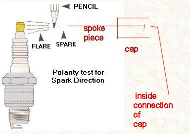
The test is difficult to see and do in brightly lit areas, and that includes inside your well-lit garage; and, outdoors. I suggest, if you do decide to do this test, that you make your SAFE SETUP in a well-lit garage. Darken the garage, and be sure you are NOT holding the pencil, nor touching anything, except starting or cranking the engine, at the time of the test.
Cap, in the photo, means the original & existing & proper value resistor type spark plug cap AND its insulated wire to the ignition coil. The spoke piece is inserted into the cap in place of the spark plug threaded top. NOTE that I captured the sketch of the spark plug off the Internet, so here it is shown with a snap top style, while the Airheads use the THREADED top style. Use the threaded style you already have. You can add the threaded snap type cover OR NOT...it is NOT needed.
This procedure is SAFEST done by not touching anything after you make the setup. Making the setup means you will be fashioning a well-insulated method to hold the items in place at the proper distance between them. Clear plastic pieces work fine. Wood items may be OK if the wood is very dry. SAFETY demands that you NOT USE GLOVES...KEEP AWAY FROM THE SETUP WHEN IT IS ENERGIZED!
1. Do this procedure at one spark plug. You can do the test and then repeat the test at the other spark plug, if you wish, after replacing the first test spark plug cap onto the spark plug in normal position. Leave the spark plugs installed in the engine. Remove one spark plug resistor cap from the spark plug. Insert a piece of threaded spoke into the spark plug cap. You can use something besides an old piece of threaded spoke, but the item, a small diameter rod or threaded rod, must be secure into the spark plug cap. The idea is to have the ignition output, THROUGH THE CAP RESISTANCE, available for making a spark gap. Sharpen the end of the spoke or rod piece a bit. DO NOT allow the spoke or other rod fitment to be able to be dislodged during engine starting and running!
2. Set things up so that the spoke piece slightly sharpened end is at 3/8" from the closest metal of the spark plug top. You must be absolutely certain that the distance is not too great, as you MUST be able to have the spark jump from the spoke to the spark plug top. You do NOT want the high voltage generated without a spark happening, as it could damage the ignition system. Make your setup so that the spark plug cable, cap, and spoke piece, are all sturdy and will not move out of position. This is very important to protect the ignition system. I suggest small pieces of plastic or dry wood, and using clamping or whatever you have available.
3. Sharpen a standard graphite pencil...yes, an old-fashioned wood & graphite center pencil. A nice longish point of the graphite is best. Do NOT use specialty pencils, nor pencils with metallic covering, etc. Keep in mind that you must have something highly insulated that is supporting the pencil, because the pencil graphite lead inside the pencil will conduct high voltage all over the pencil, as may any paint or othe pencil covering. All this means that you must also have your fashioned method such as to hold the sharpened pencil tip graphite core between the spark plug top and the high voltage wire. The pencil graphite core must not touch either. The pencil must NOT lay or be close to the metal of the engine. Suspending the pencil vertically and securely by using a piece of thin string works OK, or using non-conductive tape (no metallic duct tape!), etc. Take time to do your setup properly.
4. Remember to be sure the distance is 3/8" from spoke tip to the spark plug top metal. If you can, use an even smaller gap, I've been able to use about 1/4". NOW, back away from the test setup, due to the high voltage that will be developed. Darken your garage area, and...remember!...keep away from the setup!....>>>turn on the ignition. Crank the engine or otherwise cause the ignition system to fire. The spark between the spoke & plug top threads must be such that the spark sprays between pencil & plug top, & NOT between pencil & spoke piece. If the spark sprays between pencil graphite core and spoke piece, then the polarity is wrong. Spray, between pencil and spark plug in this test means the electricity is negative.
You can NOT get correct polarity at BOTH spark plugs if you have a TWO tower coil.
Revisions:
04/15/2003: MAJOR revision. Combine ignitiontheory.htm and ignitionsystems.htm, and major editing.
11/28/2006: Add paragraph explaining points amplifiers.
01/07/2009: Revise entire article for clarity.
10/03/2009: Again revise for more clarity, and more technical details this time too.
01/25/2010: Add Nerdy section.
01/28/2010: Expand a bit on CDI.
06/13/2011: Revise for clarity.
10/05/2012: Add language button, update Google Ad-Sense code; improve clarity in a number of places.
11/28/2012: Add QR code, inadvertently left off the above revision.
02/12/2012: Revise entire article for better clarity, and remove a FEW extraneous things.
02/16/2013: Clarity; expand info on condenser, resonant circuit, and other details.
03/09/2014: Revise entire article for clarity, and adding more nerdy comments, clarify existing ones, etc.
09/15/2014: Revise to improve clarity even more. A few technical changes, fix typos, etc. NO serious changes to technical details. Change order in which certain paragraphs/sections appear.
03/19/2015: Add section on polarity determination, and some changes in rest of article to direct to that area.
11/08/2015: Clarity improvements
03/05/2016: Update meta-codes, layout.
07/30/2016: Update metacodes and scripts. Improve explanations. Add sketch. Improve layout and fonts.
11/30/2016: Add a note to info on Accel....to see info in References.
01/31/2018: Revise entire article. Layout & sections moved. Fonts, colors & html excesses reduced. Considerably better explanations. Reduce redundancies. Margins increased to 10 pxls.
04/16/2020: Cleanup and improve explanations.
� Copyright 2020, R. Fleischer
Return to Technical Articles LIST Page
Return to HomePageLast check/edit: Monday, August 30, 2021