
|
|
The advertisements above are Google-sponsored.
Clicking on them and clicking on things inside those
advertisements helps support this website.
...AND....and thanks for your donations!
The Dell'Orto Carburetor
BMW R90S Airhead motorcycles, other bikes, & some cars!
(Extensively covering Dell'Orto functions & operation;
especially for needle/slide types carburetors).
https://bmwmotorcycletech.info/dell.htm
13
� Copyright 2021, R. Fleischer (my portions only)
There are many sketches and drawings in this article. Allow time to load if you are on a slow connection. There are comments from me scattered in the article.
>>>>>>Near the very end of this article is information from me on adjustments for the R90S carburetors>>>>>>
All the technical information on this site is:

You may be interested in reading this page, as it has all sorts of information on how I run this site:
DONATING
References:
In black and white:
http://web.tiscali.it/abosco/moto/carb/dellorto/dellorto.html
http://www.ducatimeccanica.com/dellorto_guide/dellorto.html
http://www.ducatimeccanica.com/dellorto/dellorto_manual3.html
That is a link to page 3 of that manual (you can modify that url for the home page or other manual pages), showing the fuel level adjustment. See also section 2, in the generic Dell information well below.
http://www.ducatimeccanica.com/dellorto_jetting/dellorto_parts_book.html
http://www.guzzitek.org/documents/carburateur/DellOrtoMAJ01.pdf
Besides the main article, below; which has my notes, etc., in it, you may want to overload yourself (?) by reading these two articles, which are from the DellOrto manuals themselves. These are .pdf files, so are very usable.
https://bmwmotorcycletech.info/dellorto_manual_features_and_tunings.pdf
https://bmwmotorcycletech.info/dellorto_manual.pdf
If you can stomach all this reading and absorb and understand it all ...you could become a DellOrto expert!
This is a link to an article I am hosting on this website. It contains a workshop parts list for the Dell carburetor used on the R90s, and, some information on how the carburetor works. It is fairly complete, but short and to the point:
DellOrtoAtelier.pdf
Be sure to see the information on the floats, it does pertain to Airheads, this is in section 3.2.2. See also near the very end of the long article below that you are reading, where there is my information on the pump setting and float setting, as pertains to BMW Airheads specifically! There are hints there too!
The following information article came from, I was told, the .startwin.com site, and was sent to me in a zip file, which I have unzipped, modified, and put below. I have been unable to find the author or person who might, or might not, have copyrighted this information, so as to gain official permission to place it here. This article, whatever its original source, appears to be public property. I tried to make sure about that, so, on 10-06-2003, I sent e-mails to Van Star Twin Motors, the Startwin.com folks, asking about use and copyright. There has never been a reply. I last viewed their website in November 2017, and there is nothing about the carburetors.
I have added my own comments to the article prefixed by ***, and underlined. I have corrected many typographical errors and misspellings in the original article ...and changed to U.S. type English spelling and usage. I have also eliminated some in-article hyperlinking, etc. There are places that my comments now are not all that clearly identified, as I wished to eliminate red color I used in earlier versions of this article, which resulted in gaudiness and an unprofessional look to the article; so this latest version generally uses asterisks and underlines for personal comments by me as well as for normal emphasis. I have also modified how the original's photos are formatted and placed, and added borders, and I also prevented wrapping of text around the photos. This article is best viewed on a desktop computer having a 17 inch or larger monitor screen, although I have added code to allow 'reasonable' useability on smaller screens, including tablets and smart phones.
This article can be quite useful for those trying to understand how any carburetor works. While the information does not deal directly with Constant Velocity carburetors, it does deal with needle & slide carburetors, & a vast percentage of the information applies to all types.

A GUIDE TO THE CHOICE, SETTING AND USE OF TAPERED NEEDLE MOTORCYCLE CARBURETORS
| 1 | FUNCTIONS OF THE CARBURETOR |
| 2 | FEATURES |
| 2.1 | Carburetor diagram and principal parts |
| 2.2 | Operating ranges |
| 2.3 | Installation angles |
| 2.4 | Engine connections |
| 2.5 | Air Intakes |
| 2.6 | Construction materials |
| 3 | OPERATION, SELECTION OF CORRECT PARTS, TUNING AND USE |
| 3.1 | The venturi effect |
| 3.1.1 | Selection of the correct carburetor size |
| 3.2 | Fuel supply system |
| 3.2.1 | Selection of the needle valve size |
| 3.2.2 | Selection of the float |
| 3.3 | Starting from cold |
| 3.3.1 | Independent starting circuit |
| 3.3.2 | Selection of starter emulsion tube and starter jet |
| 3.3.3 | The flooding plunger starting device |
| 3.4 | Idle systems |
| 3.4.1 | Setting the idle with a mixture adjusting-screw |
| 3.4.2 | Setting the idle with an air adjusting-screw |
| 3.4.3 | Selection of the correct size of idle jet |
| 3.5 | Progression system |
| 3.6 | Full throttle operation |
| 3.6.1 | Full throttle system as usually used on two-stroke engines |
| 3.6.2 | Full throttle system as usually used on four-stroke engines |
| 3.6.3 | Selection of the throttle valve cutaway |
| 3.6.4 | Selection of the tapered needle |
| 3.6.5 | Selection of the correct size main jet |
| 3.7 | Acceleration mechanism |
| 3.7.1 | Diaphragm accelerator pump |
| 3.7.2 | Selection of correct pump cam and pump jet |
| 3.7.3 | Piston type accelerator pump |
| 4 | MULTI-CYLINDER ENGINES |
| 4.1 | Idle tuning and adjustment |
| 5. | FACTORS WHICH CAN ALSO AFFECT THE CARBURATION |
| 5.1 | Changes of fuel |
| 5.2 | Changes in atmospheric pressure and air temperature |
1. FUNCTIONS OF THE CARBURETOR
The main carburetor functions are:
— To form a proper homogeneous inflammable mixture of fuel and air
— To supply the engine with varying amounts of this mixture
The fuel-air mixture is formed through vaporizing and by uniformly spraying fuel into the
airstream or at least by atomizing it into very small droplets.
Atomization takes place in this way: liquid fuel from the atomizer nozzle meets the flow
of air which carries it, broken into very fine droplets, to the combustion chamber.
We have spoken of a "proper" mixture because the mixture strength, defined as the
amount of air in weight mixed with a fuel unit of weight, must have a precise value, ie it
must be within the limits of inflammability so that the mixture can be easily ignited by
the spark in the combustion chamber.
lnflammability limits for commercial gasoline are: 7:1 (rich limit ie. 7 kgs of air and 1 kg
of gasoline), down to 20:1 (lean limit ie. 20 kgs of air and 1 kg of gasoline).
To obtain optimum combustion between these inflammability limits, a value very close to
the so-called stoichiometric value is needed ie. about 14.5 - 15.0 kgs of air to 1 kg of petrol.
A stoichiometric mixture ratio is one which ensures complete combustion of fuel with only
the formation of water and carbon dioxide.
The stoichiometric mixture ratio depends on the kind of fuel used, so if the fuel is changed,
this fuel-air ratio will also change (see SECTION 5.1).
The selection of the fuel-air ratio is therefore very important both for engine performance
and for exhaust emission levels.
The throttle valve (usually a flat or piston-type gate valve, also called a slide) is the main
part by which the engine is tuned ie. the engine power output is varied by controlling the
amount of mixture being drawn into the cylinder.
During bench tests, the engine is usually run in top gear in two characteristic conditions;
full throttle and part throttle.
The full throttle test simulates conditions for a vehicle on a progressive climb with the
throttle wide open.
In the bench test, this condition is reproduced by running the engine with the throttle fully
open; from this maximum horsepower condition, the engine is braked at various speeds
and the specific power and consumption figures are taken.
The part throttle test simulates the conditions for vehicle on a level road at varying speeds.
On the test bench, this condition is simulated by running the engine again from the maximum
engine power conditions, but progressively closing the throttle valve of the carburetor.
At various speeds, specific power and consumption figures are taken again.
2. FEATURES
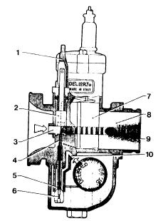
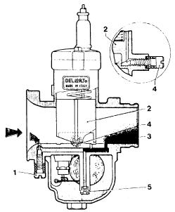
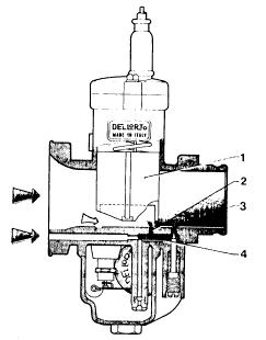
2.1 Carburetor diagram and principal parts
fig. 1 (two sketches)
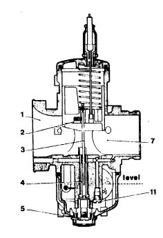
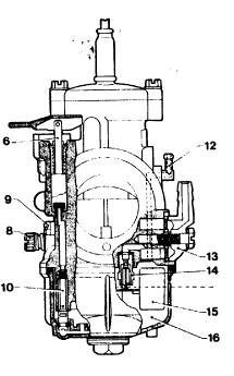
1 - air intake
2 - throttle valve
3 - tapered needle
4 - atomizer and needle jet
5 - main jet
6 - starting device
7 - venturi
8 - idle speed adjusting-screw
9 - idle mixture adjusting-screw
10 - starter jet
11 -idle jet
12 - float chamber vent
13 - fuel inlet banjo union
14 - needle valve
15 -float
16- float chamber
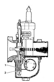
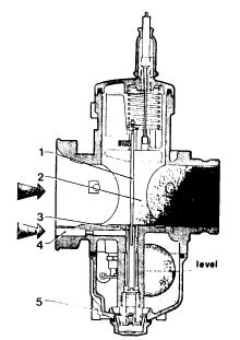
2.2 Operating ranges. Scheme of phases while running.
fig. 2
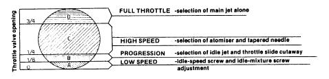
Figure 2 shows the section of a venturi according to the operating periods regulated by the throttle valve opening. In every phase of operation, it is possible to vary and select the optimum setting.
In the idle stage, the idle circuit and idle adjustment is set with the mixture screw and idle-speed screw.
***NOTE: for the BMW airhead motorcycle, the beginning setting is mixture screw 1-1/2 turns out from lightly seated, and idle screw set one full turn inwards from point it just begins to lift the slide.
In the "B" progression phase, fuel mixture delivery from the idle hole is steadily replaced by mixture delivery from the progression hole, drawing emulsion mixture from the idle circuit, and in this range, choosing the correct idle jet and throttleslide cutaway is necessary. The throttle valve cutaway slightly affects the carburation up to about half throttle.
In the "C" high-speed period, mixture delivery from the idle circuit and from the progression hole is replaced by mixture from the main circuit and selection of both the atomizer and the tapered needle should then be made.
In the "D" period of full throttle and, with all the circuits of the earlier periods operating correctly, the size of the main jet is now finally selected.
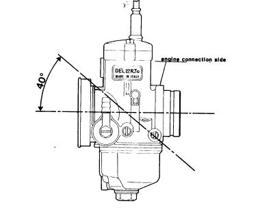
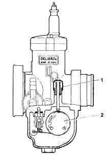
2.3 Installation angles:
The tapered-needle-type carburetors with concentric, central float chambers have a horizontal main barrel & can be mounted up to a maximum inclination of 40 degrees from the horizontal (figure 3). For applications on motocross and trials engines, etc, this inclination should be 30 degrees or less.
fig. 3
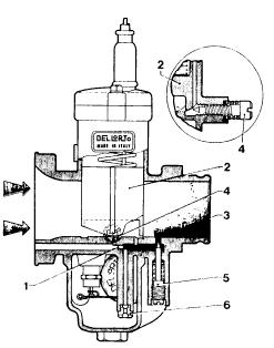
2.4 Engine connections
The carburetor is usually connected to the engine with one of the following: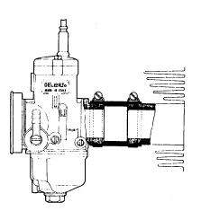
fig. 5
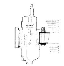
fig. 6
2.5 Air intakes
Different air intake arrangements are possible for each type of carburetor:
Open air intakes; Trumpets of various shapes and lengths; Aircleaners and filter-silencers. As far as the lengths of the trumpets is concerned, remember that short trumpets are usually used on carburetors for two-stroke engines and longer ones on carburetors for four-stroke engines.
For particular requirements, such as on some racing engines, carburetors with air intakes having a special shape are available eg PHBE H and PHM H models. On motorcycles with simple aircleaners or air filter-silencers, it is extremely important to check on the efficiency of the filter and for perfect sealing of the filter box to prevent damage to the engine and to the carburetor. Any change in the filter-silencer may produce a change in the carburation and consequently fresh adjustment and tuning of the carburetor may then become necessary. Remember also that replacing the filter or silencer with a trumpet usually results in an increase in the amount of air drawn into the engine and consequently there should also be a suitable increase in the size of the main jet fitted.
2.6 Construction materials
The carburetor bodies are diecast in aluminum or zamak ***(zinc) alloys.
For special weight-conscious requirements, there are some small-volume carburetors in elektron ***(magnesium) alloy.
All the setting parts such as the jets, atomizers, needle-valve seats, etc are made of brass.
3.1 The venturi effect
In the carburetor, the venturi is the part which allows the conversion of some of the kinetic energy of the air passing through into pressure energy.
Usually the choke ***(meaning the restriction, not a enrichening device) is shaped like a tube with a converging-diverging venturi section; in the restricted section or throat, the air pressure becomes lower, causing an influx of fuel upwards through the jets and orifices.
In tapered-needle type carburetors, there is no real choke and it has become customary to call the main intake barrel the choke.
***(the 'choke' meaning a choked-down section as used here, is not universally used in the U.S by that word 'choke'.....usually in U.S. it is VENTURI).
fig. 7
The throttle slide is fitted in the main barrel and fuel is delivered by the various circuits during the different operating periods. It is very important that the carburetor supplies a fuel-air mixture which remains constant during the changes in throttle opening and under the different load conditions of the motorcycle engine.Passage of fuel from the float chamber to the main barrel is brought about by the pressure difference existing between the float chamber and in the barrel itself; this fuel movement takes place because the float chamber is at atmospheric pressure while, as previously mentioned, the pressure is lower in the choke (figure 7).
3.1.1 Selection of the correct carburetor choke size
fig. 8
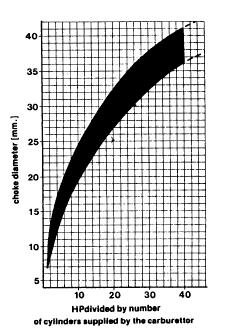
In the tapered-needle type carburetor, the choke size is the diameter of the section immediately upstream or downstream of the throttle
valve and its size is cast on the nameplate together with the model type of carburetor eg PHBE 36BS signifies a 36 mm venturi carburetor. An initial selection of the optimum choke size can be made with the help of the graph in figure 8, where a range of possible carburetor
sizes in relation to the anticipated power output per cylinder of the engine is suggested. For example, for a two-cylinder 60 HP engine ie. 60/2=30 HP per cylinder, the suggested size range is between 32 & 38mm. — a larger-size carburetor generally allows more power at high rpm ie. a higher maximum speed. However, simply fitting just a larger carburetor may not bring about the desired increase in power output as this often only follows from several additional engine modifications, each designed to improve some other aspect of the engine's performance. — a smaller carburetor will give better pickup and therefore in selecting a choke size, you should always balance your power and acceleration requirements. — usually in conversions an increase in the carburetor size also requires an increase in the main jet size of about 10 % for each 1 mm increase in the choke size, without changing the other setting parts.
— on a modified engine, whenever you require a carburetor larger than the original, it is preferable to use one which has already been set up for a similar engine ie. an engine having the same operation (two or four stroke), a similar power output and similar cylinder displacement, in order to have a good comparable base for subsequent tuning.
— tuning of racing engines is best carried out on the racing circuit with well run-in engines which are thoroughly warmed up.
3.2 Fuel system
First of all, ensure that, with the engine running, fuel flows continuously from the tank to the carburetor as vibrations from the engine or from the road surface could reduce fuel flow.
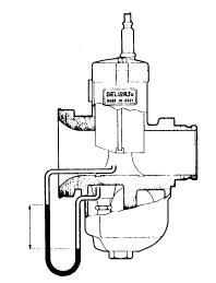
fig. 9
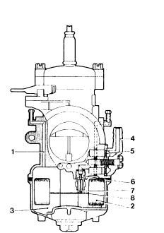
It is therefore advisable to use fuel taps and pipes of adequately large size. Further, check that fuel filter (5) in the union banjo (4) of the
carburetor is clean. Fuel from the tank supplies the carburetor (fig.9) through a valve in which a float-controlled needle operates (2).
The inlet valve has a brass valve seat inserted (6) where the needle-valve (7) regulates the entry of fuel, pushed upwards by the float by means of the float fork (8) until fuel has reached the specified level. During engine operation, this provides a constant fuel level in the float chamber so that the distance fuel has to rise to reach the venturi from the various circuits is also constant. It is important that this level is always constant throughout the operating range because, with a constant depression in the venturi, a rise in the float chamber level would cause an increase in fuel delivery and consequently enrich the mixture; conversely, lowering of the float level causes a weakening of the mixture.
Fuel in the float chamber (3) is always at atmospheric pressure because of the vent holes (1).
3.2.1 Selection of the needle valve size
For a motorcycle with gravity feed from a fuel tank, the fuel inlet valve size, stamped on the seat of the needle-valve itself, should always be 30 % greater than the main jet size.
In case of malfunctioning, you may find that the needle valve size is too small when running the engine at full throttle for a long stretch and that the engine rpm falls, due to the progressive weakening of the carburation.
Conversely, you may get repeated flooding in use where the needle valve seat size is too large.
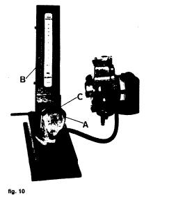
fig. 10
On a motorcycle where fuel is supplied to the carburetor via a fuel pump, a needle valve of smaller size than the main jet is required
because the boost pressure is much greater than the pressure head obtainable with the gravity tank. To avoid the troubles which
could be caused by excessive pressure produced by the pump ie. from flooding, it is possible to fit a two-way union to the carburetor thus permitting excess fuel to return to the tank. However, it is advisable then to insert a restrictor in the return pipe which reduces
the return flow, assuring an adequate supply of fuel to the carburetor still. Different types of needle valve are available: metal or
Viton-rubber-tipped, rigid or spring-loaded needle valve for different applications. For carburetors for motocross, trials, etc, or for
engines subject to strong vibrations, spring-loaded valves are required. Needle valve assemblies are supplied individually packed and tested, so it is not advisable to interchange needles and seats with other different sizes and types.
Check the needle valves for leakage with a vacuum gauge (fig. 10), consisting of an air pump A and a mercury manometer B.
Connect the vacuum gauge pipe and the fuel union firmly and hold the carburetor in the position shown In the picture. After having primed the air pump of the vacuum gauge by means of the cam C, you will see the mercury in the column rising due to the action of air compressed by the pump; if the mercury column tends to go down, check the complete fuel circuit for leakage; if the fuel circuit is in good working order, the pressure leakage is due to the needle-valve and therefore check it for wear or obstruction and, if necessary, replace it
with a complete new assembly of the appropriate size and type.
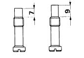
3.2.2 Selection of the float
The floats currently used are:
— dual floats connected together (figure 11)
— floats with separate parts (figure 12)
In the first type, the floats operate together, while in the second type they can move independently along two guides in the float chamber.
fig. 11 (left) fig. 12 (right)
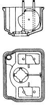
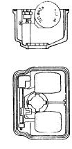
This latter type is particularly suitable for carburetors on racing motorcycles because it maintains a constant level even in the most arduous conditions of use.****The second type was used in one of Bing's arguments, for selling, aftermarket, a dual independent float kits.
Both types (of Dell'orto carburetors) are usually available with two different weights:
— a light float to obtain a low level (for two-stroke engines) — a heavy float to produce a higher level (for four stroke engines).
For all floats connected together and floats with independent parts, check the weight marked on them is correct and check that the first type is free to rotate on its pivot pin and is undamaged and that the second ones move freely along their guides and that the separate float arm is undamaged and is free to rotate on its pivot pin.
fig. 13
fig. 14
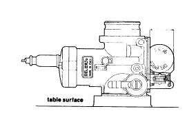
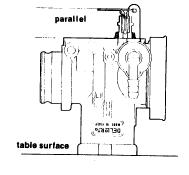
Check the correct float level position as follows:
— for connected floats, hold the carburetor body in the position shown in fig. 13 and check that the float is at the correct distance from the carburetor body face as specified in the table.
— for the floats with independent parts, hold the carburetor upside down (fig. 14) and check that the float arm is parallel to the carburetor face.
Whenever the float or float-arm position does not correspond to the proper specified level setting or is not parallel to the float chamber face, bend the float arms carefully to set the correct position.
****note: see also:
http://www.ducatimeccanica.com/dellorto/dellorto_manual3.html
|
carburetor |
float position mm |
|
PHBG |
16,5 + 15,5 |
|
PHBL |
24,5 + 23,5 |
|
PHBH |
24,5 + 23,5 |
|
PHBE |
18,5 + 17,5 |
|
PHF |
18,5 + 17,5 |
|
PHM |
18,5 + 17,5 |
3.3 Starting from cold
Although there are normally no difficulties starting the engine when it is hot, it is necessary to alter the carburation somewhat when the engine is cold. When starting from cold, the carburetor has to deliver a fuel mixture rich enough to produce in the cylinders a mixture ratio very close to the stoichiometric ratio; due to the low engine temperature, a large part of the fuel does not atomize completely or condenses on the cold portions of the in let tracts and the cylinders themselves. It should therefore be clear that, at the moment of ignition, it is the actual fuel-air ratio which reaches the cylinder that is important and not the amount of fuel, atomized or not, delivered by the carburetor.
3.3.1. Independent starting circuit.
fig. 15
It is called independent because the starting device operates with its own circuit including a starter jet, emulsion tube and a starter valve (fig. 15). Start the engine from cold with the throttle closed (7) and the starter valve (2) opened by pulling up the lever (1). If a remote cable control is fitted instead of a lever on the carburetor, the lever should be operated fully.Vacuum present in the barrel (8) downstream of the throttle valve (7) draws mixture to be delivered through passage (9) from the duct (4) and then it further mixes with the main airflow drawn from the intake (3). This mixture is formed by fuel metered through the starter jet (6) mixed with air from channel (10) and drawn through the emulsion tube holes (5).
3.3.2. Selection of emulsion tube and starter jet
fig. 16
The operation of the independent circuit starting device can be divided into two parts:
Initially when starting, during the first few turns of the crankshaft on the kick-starter or the starter motor, the device delivers a very rich mixture.
Figure 16 shows the mixture ratio depends entirely on the variety of drillings in the emulsion tube, because air passing through holes (2) draws
up fuel which is standing in the jet well (1). In this period, the mixture strength is not determined by the starter jet size but only by the amount
of fuel contained in the well above the holes located below the float-chamber fuel level. After this, a mixture leaner than previously is delivered and this mixture reaching the combustion chamber produces the first proper running of the engine.
Figure 15 shows the mixture strength delivered through the emulsion tube depends on the size of the starter jet (6) and on the size of the air duct (10).
The channel size (4) is such that it creates an optimum vacuum in the starter valve chamber, at the emulsion tube outlet both for starting up and for the mixture required by the engine for its running and warming up. Therefore, varying the position or the size of the starter emulsion tube holes will change the amount of fuel delivered; the mixture ratio is controlled by the starter jet size and therefore a larger jet causes enrichment and vice-versa. Difficulties in starting the engine can occur when this mixture is too rich or too lean and you can see this from the spark plugs. After some starting attempts, remove the spark plugs and, if these are wet, the mixture is too rich and you will therefore need an emulsion tube with holes higher up. Conversely, if the spark plugs are found to be dry, the mixture is too lean and an emulsion tube with holes lower down is therefore needed. If the engine stalls when the engine is first started from cold before it has been running for at least a minute with the starting device on, you will need to reduce the starter jet size because of an over-rich mixture or increase it if the engine stalls because of a lean mixture. Check that the starter valve closes completely afterwards to avoid any mixture blow-by which may later disturb the carburation. Therefore check that with the starting device off, the control lever is free to move a little on its pivot pin or that, where a remote cable control is fitted, the cable has at least 1-2 mm of free play.
3.3.3 - The flooding-plunger cold starting device
fig. 17
The starting device with a flooding plunger, or tickler, is shown in figure 17 and uses the normal main and idle circuits. It is composed simply of a push button (1) which, when manually operated, holds down the float (2). This forces the fuel inlet valve open causing an influx of fuel which raises the float chamber fuel level above normal and consequently enriches the mixture. This enrichment gradually decreases as the fuel is used up and stops when the float chamber level has returned to normal. This device requires quite a lot of care from the operator because if the chamber fuel level is raised insufficiently, the engine may not start because the mixture is still excessively weak;
alternatively, if the chamber level is raised too much, the resulting over-rich mixture may also prevent the engine starting.
3.4. Idle systems ***see my end of article notes, underlined, regarding BMW airhead settings
At idle the carburetor supplies only the mixture required to keep the engine running at very moderate rpm. The engine needs only a small amount of air when idling and the throttle slide should therefore be almost completely closed. Upstream of the slide there is only a weak
vacuum, insufficient to cause the main circuit to deliver any fuel emulsion, while downstream of the slide there is a stronger vacuum which activates the idle circuit; idle circuits are designed with either a mixture-adjusting screw or with an air adjusting screw. Check that the throttle
cable has about 1 mm free play when the slide is fully closed. Always adjust the idle setting with the engine fully warm.
Screw in the idle-speed screw (4) to obtain a slightly-higher idling speed than normal (about 1200 rpm for a four-stroke engine or about 1400 rpm for a two-stroke); Then adjust the air-adjusting screw (1) to obtain the most even running.
Then unscrew the idle-speed screw again until you obtain the normal idling speed. Finally, to obtain the best engine running, it is worth rechecking by very carefully readjusting the air-adjusting screw.
3.4.1 - Idle setting with a mixture-adjusting screw
fig. 18
The adjusting screw meters the amount of mixture of a strength predetermined by the metering effect of the idle jet and the air
corrector, and therefore on screwing in the mixture screw, idle fuel delivery decreases and vice-versa. In figure 18 the throttle slide 2 is shown in the idling position, adjusted by the idle speed screw (4). In this position the vacuum present down stream of the throttle valve causes mixture to be delivered via the hole (3), regulated by the tapered tip of the mixture adjusting screw. Mixture formed from fuel metered through the idle jet (6) and air metered by the calibrated passage (1) further mixes with air regulated by the throttle slide opening. The idle mixture adjusting-screw is always located downstream at the throttle. Check that the throttle cable has about 1 mm of free play with the slide closed. Always adjust the idle setting with the engine fully warmed up. Proceed as follows:
Screw in the idle speed screw (4) to get a slightly- higher speed than normal (about 1200 rpm for four-stroke engines and about 1400 rpm for two- stroke engines); then screw the mixture adjusting screw (5) in or out until you obtain the most even running. Then unscrew the
throttle-stop screw (4) until you get the desired idle speed again. To obtain the best engine running, it is worth finally rechecking by carefully readjusting the idle mixture screw (5).
3.4.2 - Idle Setting with an air-adjusting screw
fig. 19
An idle circuit with an air adjusting-screw adjusts the amount of air required to produce the mixture that the idle circuit has to supply during idling. The air adjusting screw varies the mixture strength delivered by the idle circuit; screwing in results in a richer idle mixture and vice-versa. In figure 19 the throttle slide (2) is shown in the idle position adjusted by the idle-speed screw (4). In this position, the vacuum existing downstream of the throttle valve causes mixture to be delivered the hole (3). Mixture formed from fuel metered through the idle jet (5) and air regulated by the idle air screw (1) further mixes with air metered by the throttle slide opening. The idle air-adjusting screw is usually located up stream of the throttle slide.
3.4.3 - Selection of the correct size of idle jet
To select the proper size of idle jet, slowly open the throttle with the twistgrip (opening should not exceed a quarter throttle): a slow and uneven increase in rpm indicates that the idle jet is too small. This effect can also be observed when the idle mixture screw is open too much or
when the idle air screw is closed too much and therefore not properly responsive to the engine's running. If you observe smoke in the exhaust gas and a dull noise, it means that the idle jet size is too large; this can also occur when the mixture-adjusting screw is screwed in too
much and oversensitive or when the air-adjusting screw is screwed out too much. Usually with racing motorcycles, after having adjusted the idle as above, unscrew the idle-speed screw to allow the throttle to close completely so that you will obtain the maximum engine braking on
closing the throttle. In this case however, do not readjust the mixture screw or air-screw setting because any further mixture screw closure or air-screw opening may cause two-stroke engines to seize on the overrun.
3.5 Progression system
fig. 20
By progression we mean the transition period between mixture delivery from the idle circuit and the beginning of mixture delivery from the main jet circuit.
On first opening the throttle, the air drawn into the engine increases and therefore, in order to have an inflammable mixture still, the fuel supply must also be increased.
As previously noted, the idle hole(3) shown in figure 20, only delivers sufficient fuel for engine idle operation and the main circuit still does not deliver any fuel because of insufficient vacuum up stream of the throttle. The progression hole (2) is therefore necessary to deliver the fuel required during this transition period. The progression hole draws fuel from the idle circuit (4) and is positioned immediately upstream of the closing edge of the throttle slide (1) for the promptest response to fuel demand when the airflow suddenly increases. It is interesting to note that the progression hole serves a dual purpose: When the engine is idling, air from the main barrel passes into the progression hole and weakens the mixture flowing through the idle circuit; When the throttle is opened slightly, the idle circuit mixture flows into the main barrel through the progression hole. The progression hole therefore first feeds air in one direction and then feeds mixture in the opposite direction.
3.6 Full-throttle operation
fig. 21
Following the progression phase, on further opening of the throttle, the full-throttle circuit begins to operate. By opening the throttle valve beyond progression, a partial vacuum is created in the mixture chamber, due to the speed of the air being drawn through to the engine, and this vacuum is sufficient to cause fuel to be sucked out of the atomiser nozzle.
In this situation (figure 21), fuel metered by the main jet (5) and further regulated by the atomizer outlet (3) (the atomizer outlet area varies according to the position of the tapered-needle moving up and down through it) is mixed with air from channel (4) and air from the main barrel (2).
The amount of fuel which comes out in the first quarter of the throttle slide movement is determined by the throttle slide cutaway, by the size of the atomizer and by the diameter of the cylindrical part of the tapered-needle at the opening.
From here up to three-quarter throttle, it is determined by the atomizer-needlejet size and by the diameter of the tapered-needle at the opening.
From three-quarter throttle to full throttle the amount of fuel depends solely on the size of the main jet.
Therefore you should change the following parts to vary the full throttle circuit delivery:
— the throttle slide cutaway
— the tapered needle
— the atomizer-needlejet size and type
— the main jet
There are two different full-throttle systems; one is used on two-stroke engines and the other on four-strokes, although some special applications do not conform to this.
3.6.1 Full-throttle system usually used on two-stroke engines
fig. 22
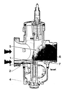
Figure 22 shows the full-throttle mechanism used on two-stroke engines which features an extended nozzle (6) at the end of the atomizer (7); this produces better performance during acceleration.
Air from the inlet (3) passes through channel (2) and flows into the round extension (1) formed by the upper outer end of the atomizer and by the inner part of the nozzle (6). It then mixes with fuel metered through the main jet (4) and coming from the atomizer (7) and then flows into the venturi (5).
A larger atomizer-needlejet size produces an increase in fuel delivery at all throttle positions and, conversely, a smaller size will produce a decrease in fuel delivery at all throttle openings.
fig. 23
Usually the atomizers on carburetors intended for two-stroke engines are manufactured in two types: with either long or short upper parts (figure 23). The atomizers with longer upper parts cause a weakening of the mixture at low speeds and during acceleration from low speed; on the other hand, atomizers with shorter upper parts produce extra enrichment. Carburetors for racing motor cycles use atomizers with short upper parts.
3.6.2. Full-Throttle system as usually used on 4-Stroke engines and also on 2-Stroke engines in special applications.
fig. 24
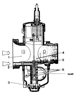
Figure 24 shows the full-throttle system used on four-stroke engines which utilizes air to change the amount of fuel delivered by atomizer following sudden throttle openings. There are several side holes (6) in the atomizer (5), communicating with the air intake (2). On opening the throttle fuel metered by the main jet (3) flows into the atomizer where it mixes with air drawn through the side holes of the atomizer and the resulting fuel-air emulsion flows into the barrel (4) where it further mixes with air coming from the main intake (1). A larger internal diameter of the needlejet atomizer produces an increase in fuel delivery at all throttle valve positions while a smaller size results in a decrease in fuel delivery at all throttle valve openings. The atomizers fitted to carburetors intended for four-stroke engines are manufactured with different types of side drillings because the positions of these holes affect acceleration response.
Atomizer holes positioned high up cause a weakening in the mixture since they are above the float chamber fuel level and only let air in; conversely, holes lower down cause mixture enrichment because they are below the chamber fuel level and draw fuel from the well to the barrel.
The result is that, to weaken the mixture under acceleration, atomizers with holes drilled higher up are required, while to enrich the mixture, atomizers with holes lower down are needed. The holes diameter determines how long the well takes to empty and it is therefore also necessary to select a suitable size.
3.6.3. Selection of the throttle valve cutaway.
fig. 25
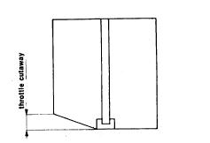
Following progression and on opening the throttle further up to approximately one-quarter, the partial vacuum present in the mixture chamber draws fuel up through the atomizer. In this operating phase the effective fuel passage area is determined by the atomizer-needlejet internal diameter and by the varying section of the tapered-needle moving up and down inside it. The deciding factor which regulates the air flow in this phase is the throttle valve cutaway (figure 25). A small cutaway creates a greater vacuum and consequently causes a larger amount of fuel to be drawn up through the atomizer ; on the other hand, a larger cutaway would lower the vacuum and therefore reduce the fuel delivered. Because of this, fitting a lower slide cutaway results in enrichment and vice versa.
3.6.4 - Selection of the tapered needle
The determining features of the tapered needles are the diameter A, length C of the tapered part, and diameter B of the tip.
fig. 26
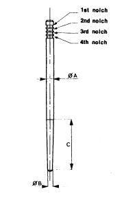
You should select the tapered needle considering the elements above in the complete operating range.
The cylindrical part of the needle affects the mixture strength in the first throttle valve movement, up to about a quarter throttle; therefore, in this operating phase, a reduction in the diameter of this cylindrical part produces a mixture enrichment and vice versa.
The tapered part of the needle affects the operating period between a quarter and three-quarter throttle; therefore, for any given tapered part length and cylindrical part diameter, increasing the tip diameter results in the mixture weakening and vice versa.
With the diameter of the tips and the cylindrical parts the same, an increase in the tapered part's length results in an advance of the enrichment of the mixture. By changing the notch positions, therefore, it is possible to raise or to lower the needle in order to obtain mixture enrichment or mixture weakening over the range regulated by the needle taper.
When major changes in the mixture strength are necessary, change the needle according to the elements and features mentioned above.
In most cases the tapered needle is always held pressed against the atomizer-needlejet's upper edge by a spring located in the throttle slide.
In this way, the position of the needle and the atomizer, and consequently also the fuel delivery, are maintained constant, and thus avoiding excessive wear both of the needle and the needlejet due to vibration. ***This is missing in the design of the Bing carburetors (CV included) and results in faster needle wear, especially on late model Bing CV carbs with aluminum needles...which not only wear their diameter, but the adjustment notches/grooves in the needle wear exceptionally fast.
***On the BMW airheads, a good starting point is the 3rd notch from the top for the needle.
3.6.5 Selection of the correct size of main jet
The correct main jet size should be selected by running on the road, preferably by first starting with an over-large size jet and gradually reducing it. At full throttle, turn the starting device (choke) on, thus further enriching the mixture and, if this produces a worsening in engine running ie. it reduces engine rpm, it is advisable to reduce the main jet size until you finally get satisfactory operation. Other signs revealing the main jet is too big are a very dark exhaust pipe, dark exhaust gases and damp spark plugs and an improvement in engine running when the fuel supply is temporarily shut off. In a case where too small a main jet has been fitted at first, and the running with the choke on makes a noticeable improvement, you should increase the main jet size until the conditions mentioned above occur.
In selecting the correct main jet, the engine running temperature should be taken into consideration, quite apart from increases in power and top speed, because lean mixtures cause higher running temperatures.
In a situation where a very large increase in the main jet size is required, remember that the main jet flow cross-sectional area should not exceed the effective area for fuel flow between the needlejet and the tapered-needle tip.
Check this with the following formula:
Where:
Dm is the main jet size
Dp is the atomizer-needlejet size
Ds is the tapered needle tip diameter
All measured in hundredths of a millimeter
For example:
main jet 180
needlejet 264
tapered needle tip 170:
Giving the result 25.430 < 32.030 ie. the needle - needlejet clearance is adequate here.
3.7 Acceleration
Every time the throttle is opened suddenly, the air speed in the barrel drops.
In two-stroke engines this does not upset good engine running, but in four-stroke engines this drop in air speed causes the atomizer to deliver insufficient fuel.
For this reason, on large-diameter carburetors for four-stroke engines, an accelerator pump enrichment device is fitted.
3.7.1 Diaphragm accelerator pump
fig. 27
As shown in figure 27, on opening the throttle slide (9), lever (8) controlled by a special cam (7) cast into the front of of the throttle slide, acts directly on the pump diaphragm ( 1), I held out by the spring (2).
This diaphragm, through the delivery valve (4) and pump jet (5), pumps fuel into the main barrel (10).
On closing the throttle, the diaphragm returns to its original position, pushed by the spring and drawing fuel up from float chamber through the inlet valve (6).
The pump injection amount can be changed by adjusting the screw (3) which controls the travel of the diaphragm and consequently the volume of fuel pumped out. The start of pump operation is determined by the particular configuration of the cam (7) cast in the front of the slide (9).
3.7.2 Selection of correct pump jet and slide pump cam
fig. 28 (left); fig. 29 (right)
The profile of the cam in the throttle slide controls the action of the accelerator pump. For example, cams having the operating ramp high up in the throttle valve (see figure 28) make the pump start to work immediately the throttle opens.
Operating ramps lower down in the slide delay the spraying action of the pump.
Having selected the cam type, to produce immediate or delayed pickup from engine idle, the pump jet size can then be chosen.
The size of pump jet selected determines the duration of fuel delivery, so the larger the pump jet used the shorter the pump spraying interval and vice versa. The quantity of fuel sprayed out has already been fixed.
Pump jet selection must be effected with the engine running with rapid full-throttle acceleration; under these circumstances the optimum jet size should allow the engine to pick up regularly and promptly, rapidly increasing engine speed in every acceleration-speed range.
3.7.3 - Piston-type accelerator pump
fig. 30
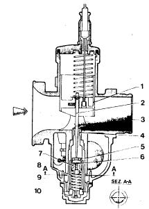
Figure 30 shows a simpler pump system than the one previously described, used on some other carburetor models.
As shown in the figure, on opening the throttle (1), the tapered-needle (2) integral with it, releases the piston (5) with its perforated top, which rises, pushed by the spring (8), squirting fuel through the atomizer (4) directly into the main barrel (3). In the upstroke, the ball-bearing valve (6) closes and seals the hole (7).
On the downstroke, the needle pushes the piston (5) down, compressing the spring (8), while the ball valve (6) rises, unblocking hole (7) so that more fuel can again fill the chamber which has been formed above the piston.
The length of the chamber where the piston (5) moves, determines the amount of fuel which is pumped up into the main barrel (3).
The pump action is also affected by the length of the grooves (9) machined in the internal walls of the cylindrical chamber, where the pump piston moves (see figure 30).
When the throttle slide stops moving in any open position, the piston (5) also stops, stopping the pump action; the carburetor therefore then works in the usual way. Fuel, which rises continuously from the float chamber by the normal partial-vacuum action and flows first through the main jet (10) and then up into the atomizer-needlejet (4) to tlg. 30 the main barrel (3), keeps the ball valve (6) open.
4. MULTI-CYLINDER ENGINES
fig. 31
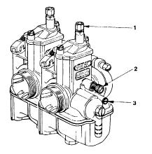
Supplying fuel mixture to multi-cylinder engines usually involves fitting one carburetor to each cylinder. This is because high-performance motorcycle engines have camshaft timing which would upset the carburation provided by just a single carburetor.
This does not happen with less sophisticated engines and, in these cases, it is possible to provide an efficient fuel supply to one or more cylinders with only a single carburetor.
Depending on the particular engine layout, installation of carburetors on multi-cylinder engines is generally accomplished in two ways:
— with carburetors separated (figure 31) and with a throttle cable each.All the adjustment procedures for multiple carburetors are the same as those described for single carburetors.
4.1 - Idle tuning and adjustment
Idle adjustments on a multi-cylinder engine with several carburetors should be carried out with a mercury manometer having a column for each carburetor.
Make sure, both for independent (figure 31) and grouped carburetors (figure 32), that each throttle cable has about 1mm free play at idle.
Now you can adjust the idle as follows:
— Connect each barrel to the mercury manometer, taking off the blanking plugs provided on the vacuum intakes and fitting instead the proper vacuum connectors. If a compensator is fitted, dismantle it and connect the compensator connections to the mercury manometer.
— unscrew each idle mixture screw (3) about two turns from the fully-closed position.
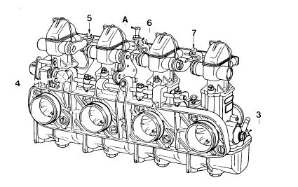
fig. 32
— for independent carburetors (figure 31) align the mercury column levels using the throttle adjusting screws (2) on each carburettor.
— for carburetors mounted together in a group (figure 32) align the mercury column levels with the level of the carburetor connected directly to the throttle control, adjusting the balance-adjusting screws (5), (6), (7).
— then adjust the mixture screws (3) of each carburetor to obtain the fastest even running.
— recheck the alignment of the mercury columns and then reset the engine to the desired idle speed using the throttle adjusting screw (2) in figure 31 or screw (4) in figure 32.
— for independent carburetors (figure 31) check that the alignment of the mercury columns is unaffected by slightly opening the throttle. If it is, adjust the individual cable-adjuster screws (1) to correct this.
— finally, disconnect the manometer unions and refit the blanking plugs or the compensator piping.
Where the carburetor group has been dismantled for servicing, some approximate synchronization will be helpful before reassembling; see that all the slides are opened 1mm and that the idle mixture screws are opened two turns from the fully-closed positions.
The throttle valve opening securing-screw (A) should be adjusted is such a way that it allows full opening of the throttle slides up to a maximum of 1mm beyond complete clearance of each carburetor barrel.
5. FACTORS WHICH CAN AFFECT CARBURATION
In some cases, carburation which has been properly set up in particular conditions can then be upset by certain factors ie.
- a change of fuel used
- a change in atmospheric pressure
- a change in air temperature
5.1 Change of fuel
When a different fuel other than commercial petrol is used, it is necessary to estimate theoretically the new stoichiometric mixture ratio & consequently change all the jet sizes to suit.
If the stoichiometric mixture ratio decreases, larger jets are required and vice versa. Any such changes should, of course, be made on a percentage basis ie. when the stoichiometric ratio in creases by a certain percentage, the jet sizes should be reduced by that percentage.
For example, if commercial petrol (stoichiometric ratio 14.5) is replaced by methyl alcohol (methanol, with chemical formula CH3OH - stoichiometric ratio 6.5) the jet sizes should be increased by about 50 % ie. double the flow rate. If fuel consisting of 25% petrol and 75% methanol is used, jet sizes should all be increased by 30 % with fuel composed of 50 % petrol and 50 % methanol, the jet sizes need only be increased by 18% compared to when using straight petrol.
You should also replace the needlevalves, increasing the seat sizes accordingly.
When using special fuels such as methanol, it is very important that all the component materials of the carburetors have been treated, wherever necessary, to resist chemical attack. For example, nylon components should be removed, and replaced by other parts resistant to the new fuel.
5.2 — Changes in atmospheric pressure and in air temperature
Variations in pressure or temperature cause a change in the air density and consequently a change in the fuel-air ratio and further tuning may therefore become necessary.
A decrease in atmospheric pressure with consequent decrease in air density causes a mixture enrichment and smaller jets will therefore be required.
Altitude variations also produce changes in the carburation and they too cause changes in the air density; prolonged use of a vehicle at an altitude higher than 1500 metres, the carburation of which was originally set up for operation at around sea level, would require a change of jet sizes in proportion to the pressure change.
In this case too, a decrease in pressure should be compensated by a reduction of the jet sizes. Furthermore, a lowering of air temperature produces an increase in air density and consequently a mixture weakening; therefore an increase in the jet sizes is required.
Summarizing, we can say that any decrease in air pressure, any increase in altitude or in air temperature should be compensated for by a decrease in the jet sizes.
Conversely, any increase in pressure or any decrease in altitude or in temperature should be compensated by an increase in the jet size.
NOTES for BMW R90S Airheads:
The R90S has a Dell model PHM 38BS on the left; and, PHM 38BD on the right.
The initial adjustment will be: needle on 3rd notch from top; mixture screw 1-1/2 turns out from lightly seated; idle speed screw at 1 turn inwards from point the slide just starts to lift; 1-2 mm of free play in throttle cables; 2-4 mm of free play on the choke cables. The choke cables are set for some free play, chokes horizontal ....which is off. Try to have the cable amounts the same, by eyeball and feel.
It is a good idea to check the float adjustment (3.2.2). Here is another method:
With the carbs full of fuel, shut off the fuel & clamp the line above the carb. Place a measuring cup under the bowl, undo the center nut, let all the fuel run into the cup. It should be 55 cc. Adjust the float if need be, taking this measurement several times, to be sure you are doing it accurately. Officially, from the manual, the float heights are 18 mm, +- 0.5 mm. You will prefer my 55 cc method; or, check the measurement on the workbench.
When overhauling or otherwise working on the Dell'Orto carburetor, it is common to have problems with the accelerator pump. Some hints:
1. The orifice goes in with the pinhole facing forward; the flat side is for indexing.
2. When installing the pump, remove the plug and pour fuel into the chamber, and with the slide removed, pump the accelerator pump until fuel streams out from the orifice.
3. You MUST get all the air out to enable the pump to work correctly.
4. To see if the accelerator pump is working at all, lift the throttle cable a full stroke amount ...see if the accelerator pump squirts fuel in the throat area.
You may or may not want to play with the accelerator pump if it looks like it is working. If you want to play ...the accelerator pump operation is a bit of a bother to set up correctly. The actual flow amount has to be measured, adjusted, measured, adjusted.
Pull the accelerator pump nozzle in the side and covering plug. Use a bit of tape over the nozzle passage inside the carb throat, and use a graduated cylinder under the boss where the plug was removed. Fuel on, pull up smoothly on throttle cable until slide fully open, lower the slide, count to five, raise slide again, continue until you see fuel in the graduate. The pump is now primed. Now empty the graduated cylinder, and begin again, counting the full strokes of the slide. The original stock setting was 0.4 cc per stroke. I consider that to be too lean; and suggest you use 0.5 to 0.6 cc per stroke. Count a number of strokes, perhaps 10 or 20, and then see what is in the graduate.
Adjustment is the little screw on the side of the pump housing ...on the top rear face of the body. Loosen locknut and turn screw in for less, out for more. Be sure the tape has not loosened and allowed fuel to flow into the engine. Seal the adjustment. If no output from the pump, check that the lever arm in the throat is engaging the ramp in the slide and check the condition of the ball valve in the float bowl ...the brass thing sticking down. Unscrew it and clean with a strong solvent. As mounted direction, flow should be free up, and none down.
Parts and information:
Herdan Corp.
Port Clinton, PA
https://www.herdan.com/dellorto/
Any BMW bike dealership could probably order the parts for these carbs as used on the R90S. The carb & parts distributor for the U.S. is Hermy's BMW, Port Clinton, PA. See just above...
Here is a Ducati Dell parts source.....lots of Dell stuff that fits your Airhead:
https://store.bevelheaven.com/
REV:
10/06/2003; 5:58 p.m.: Updated with several links, and the full Dell'Orto article, make hyperlinks, check that they work.
01/21/2004: Update for U.S. English and notes on BMW Airheads initial adjustments.
09/06/2004: Add note on float adjustments and a link; fix bad drawing on figure 1 (upper).
01/04/2005: Add emphasis, rearrange top of article very slightly.
02/17/2005: Fix all sorts of hyperlink problems and fix format and some minor typos.
03/05/2005: Slight updates on airheads adjustments.
02/18/2007: Correct a few minor typos, add some references to specific places in this article; modify meta items.
04/19/2007: Minor corrections.
01/20/2008: Minor clarifications and add Herdan; modify Google advertising, modify description, title, keywords.
03/10/2008: Add this hyperlink, and explanation:
http://www.bmwmcnj.com/Technical/dellorto-carb-manual.pdf.
04/16/2010: Clean up appearance, fix faulty sections of links.
06/17/2011: Clean up many places where captions & text do not correspond correctly or next to, or about, the figures.
06/23/2011: Add links to the Dell's factory manuals, which are now on this site.
07/12/2011: Add more information on Hermy's.
09/24/2012: Add QR code; add language button; change Google code.
12/02/2012: Clean up for smaller screens. Some hidden code changes. Remove this link as it is dead, and no link on the shortened URL either:
http://www.bmwmcnj.com/Technical/dellorto-carb-manual.pdf
2013: Remove language button, as the Scripting was causing problems with some browsers.
08/2015: Change wording on adjusting acceleration pump, and amount.
02/08/2016: Update meta-codes. Left side justification. Clean up, etc.
05/27/2016: Layout, fonts, metacode, scripting changes.
10/15/2017: Remove colors and bolds; remove photos text wrapping; edit format. Fix so article displays OK on all devices; clean up excessive and old HTML, etc.
04/11/2019: Add parts source https://store.bevelheaven.com/
03/15/2021: Clarify information on the acceleration pump, in the area between lines 973 and 977 (this area is near the end of this article)
� copyright 2021, R. Fleischer (my portions only)
Return to Technical Articles LIST Page
Last check/edit: Friday, April 12, 2024