
|
|
The ads above are Google-sponsored.
Clicking on them at every visit helps support this website!
Clicking on something INSIDE an advertisement helps even more!
Also, thank you for the donations! Donating
Making the Bosch and Wehrle Metal Can Electronic
Voltage Regulators Adjustable.
>>A HOW-TO article<<
� Copyright 2020, R. Fleischer
https://bmwmotorcycletech.info/boschelreg.htm
22
I wrote this article because a few people asked. You can purchase an adjustable voltage regulator quite reasonably from http://www.rockypointcycle.com or https://www.euromotoelectrics.com or perhaps even cheaper from Amazon. Most of those will have a metal case, but epoxied or tar embedded innards, but the adjustment is easy to get to. But, the stock metal can regulators are not difficult to modify, the cost is very low, and you get to keep the original stock appearance ...if you want-to. The metal-can VR's are very reliable. They can even be modified to work with very high powered alternators for the Airheads (by changing the power transistor inside).
The BOSCH and Wehrle METAL CAN Electronic Regulators ARE relatively easy to modify, so, go ahead if you wish-to. YES, there are metal can regulators that have a Wehrle label on top, the ones I have seen are stamped with model E 1051 B/14V, made in Germany. These regulators have a similar circuit to the Bosch regulator which is what the following procedure is specifically for, although applicable to the Wehrle. This Wehrle metal can regulator has the same sort of circuitry & adjustment control inside. These regulators, no matter the name on them, MIGHT have been made by either Bosch or Wehrle.
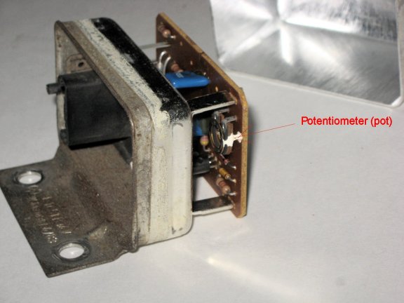
The exact same procedure is involved....(and the same hole drilling and adding a grommet IF YOU WANT TO) ...etc. Here is a photo of the Wehrle METAL CAN Electronic Regulator, with the potentiometer, with factory sealing paint.
This how-to article's purpose is to make your Bosch or Wehrle ELECTRONIC metal can unit easily adjustable. This is NOT for the similar but taller metal can mechanical Bosch regulator...see https://bmwmotorcycletech.info/boschmechreg.htm
Also found on this website is an article on increasing the voltage output of the plastic-cased Wehrle. This article applies to BMW Airhead Motorcycles, but is also applicable to any other vehicle that uses these metal can electronic voltage regulators. There are several methods to increase the voltage, which is the usual desire, including adding a tiny diode to 'fool' the regulator, but the method described below makes it fully adjustable, is simple, and works very well. Don't attempt this if you can't work on small parts and comfortably use a small soldering iron. You MAY not need the soldering iron! You do not have to drill the hole in the cover, but that makes the regulator MUCH easier to adjust. Parts needed (maybe): 1. One thin-metal chassis-hole-mounting type of rubber grommet with a central hole....no special size, from Radio Shack or ? One using a 3/8" mounting hole is fine, so is one of 1/4" or 5/16". The 3/8" or even a 1/2" might be better if you are not good at making measurements on where to drill....so read this procedure through. You don't HAVE TO have a grommet, but you probably WILL want it, and I recommend it. You will also want a common black plastic body-plug that fits the center of the grommet hole ....or, you could use tape. A plug is nicer. When the adjustment is all done, use a tiny bit of RTV cement is to seal the plug so it stays in place. Read this entire article first, to decide if you will drill and get a grommet ....or not. The electronic metal can voltage regulator consists of a number of transistors, diodes, resistors & capacitors, the purpose of which are not important to this article. The Modification: 1. Remove the fuel tank and then the voltage regulator from the bike. There are two allen head screws to remove from the VR, and a plug (with a release tab) to disconnect. You don't have to remove or disconnect any battery connections. 2. Remove the tape from the regulator that keeps the top can from coming off. 3. Gently wiggle the top can off the base, these can be on tight, so work slowly. 4. Inside you will find a printed circuit board with all the components mounted upside down ....that is, underneath the board. On the end of the board OPPOSITE the plug/socket end, you will find a small electrical device called a pot (short for potentiometer). This is the factory adjustment control. Every one I have seen is always sealed with a drop of a hard-to-remove white paint. 5. Try to remove or at least release the paint drop with repeated use of a WOOD-TUBE type Q-tip (some Q-tips use plastic tubing or plastic rod, that will dissolve in a solvent!) or a large common wooden toothpick, in something like acetone, MEK, or paint-remover-gel. Clean off any gel, if you used that. This can take some time. If you are successful in not damaging the pot, it will be usable as is, and then can be adjusted. If you are not successful, you can THEN, paint droplet still wet from the solvent/gel, try VERY GENTLY prying a tiny bit at the paint, to free up the lower adjustment fingers metal ring. Do NOT pry much. I use a dental pick tool. As a last try before replacement, I have found it best to CAREFULLY unsolder the three legs of the pot and remove it, & soak it in acetone for a short while ....which ALSO gives me SAFE access to ENLARGE the very tiny hole for the adjustment, that is stock, on the board. If you are careful you could leave the pot in place & drill out that hole by hand...just don't ruin the pot. You don't HAVE to drill the tiny hole larger, but you will then need a VERY TINY jewelers screwdriver for the adjustment,....so I DO recommend drilling the board hole larger. What size? Whatever you wish, to match your jeweler's screwdriver (or a modified nail) that FITS THE POT SLOT. If you ruin the pot, it will have to be replaced, with any common 100 ohm pot that fits, or can be made to fit. Try to be very careful, & not ruin the existing potentiometer! 6. Assuming the pot is operational, or the replacement will be installed; carefully enlarge the the circuit board existing hole for access by a larger sized jewelers screwdriver. If you intend to make the regulator adjustable from outside the can (recommended), then you have an optional step to do now. That is to drill the thin metal cover in the appropriate place, and install a rubber grommet in the drilled hole. The purpose of the rubber grommet is to keep you from electrically shorting the potentiometer metal to the regulator cover metal when adjusting the voltage regulator with a metal-shank screwdriver. You don't have to have the hole in the top of the can & grommet because you could set the regulator without the cover on. The cover, whether on or off, has NO magnetic effects on the adjustment, so you CAN install the VR, make the adjustment with a very tiny jewelers screwdriver (cover off), and then simply replace the cover, using sealing tape. This completely negates any need for drilling or a grommet. It is your choice. You can always add the hole and grommet later, if you want to. Drilling the thin can metal, should you decided to do that, needs to be done with progressively larger drills or other tools, to avoid the drill from 'grabbing' the thin metal. You WILL find the can hole convenient, but not absolutely necessary, for now ....and for future adjustments ....such as if you change the battery to a type needing a different voltage. The more or less standard 13.8 volts as VR's typically come from BMW, is TOO LOW for modern batteries; and, I think it too low for the original flooded batteries. If you use the hole & grommet, it's nice to seal it's hole with something. I use, as noted well-above, a common black plastic or rubber auto-body plug, that fits into the grommet center hole, and I use a dab of silicon rubber sealant ...that stuff in a squeeze tube ....to keep that plug in place. Easy to remove & readjust whenever you might like to, and the regulator remains weatherproof. DO NOT mix up the information on the two holes. 7. Be sure all is assembled correctly. Re-check your work. Install the grommeted cover (if so done); be sure your jeweler's screwdriver will fit the pot slot rotate the pot back and forth a wee bit. If you are worried about the pot being OK, you could use an ohmmeter to prove that the pot is about 100 ohms between the ends, & that the wiper, with respect to either end, works properly on the ohmmeter as you rotate the pot wiper, before re-installing the metal cover. 8. Install the regulator on your bike & plug the cable into it. If you did not drill the metal cover hole (and installed the grommet), leave the cover off and adjust the VR, ....then replace the cover and tape. 9. Adjustment of the regulator is by the jeweler's screwdriver, making SURE the metal of the jeweler's screwdriver can NOT contact the metal can (if can is ON, then you now know why I said to use a grommet). The screwdriver MUST be the right size, or you will ruin the pot. Be very gentle in any downward pressure when trying to engage the pot. The screwdriver works by fitting into a slot in the pot, to rotate the pot contact fingers. 10. The voltage setting depends on your usage of the bike, the type of battery, & the temperature of the regulator when making the adjustment. Regulators are supposedly temperature compensated & thus DESIGNED to INcrease its voltage very slightly as the
temperature of THE REGULATOR goes down. Some don't do this well, so do the adjustments with the VR when cool, engine having been off before adjustment began. Some guidelines & hints: I will assume the engine will be started & regulator adjusted within a FEW minutes after starting (so the regulator has NOT warmed up from engine heat). The GOOD battery, load test if unsure, is fully charged or very nearly so to begin with. Just because your battery SEEMS good does NOT mean it is good enough for a VR adjustment ....so I suggest you fully charge the battery, let it sit 2 hours, and then do a formal Load Test, using a load tester, perhaps from Harbor Freight Company (their 2-meter version is quite decent). The voltage must be set via a digital voltmeter connected AT the BATTERY TERMINALS.
Start the bike. With only the starting-up battery drain, & the bike at perhaps 3500-3800 rpm for a minute or so, adjust the the pot thusly: For common flooded batteries, a good compromise (between water usage and charging) is 14.1 volts at 70�F as measured on the VR case. For temperatures at the regulator metal can when you adjust it: SOME types of sealed AGM/VRLA batteries can successfully use 14.5 to 14.9 volts at 70�F. Check your battery maker's specifications. I would not use over 14.5 for long distance touring. All voltage readings are taken AT THE BATTERY terminals themselves. Do not connect to the wire/lugs connected at the battery and do NOT use your fairing voltmeter. You must have an accurate digital voltmeter. Your battery connections to the bike's system must be clean, solid, etc. If you have corrosion or connection problems ANYplace in the system, or even a wonky ignition switch, voltage regulation may be poor. Suspect places are the battery terminals, battery wires (especially internally within 2 inches of the + terminal), the starter relay plug & wiring there, the ignition switch. Also check the large red wire that plugs into the diode board on the right side as you face the board from the front of the bike, and do check the tightness of these
connections including the alternator phase wire plugs. Problems with the VR & output will also come from poor grounding of the diode board. If you have rubber diode board mounts, get rid of them & install aftermarket mounts BEFORE you do any VR adjusting. Article is on this website. NERDY: Interested in what ONE COMMON VERSION of an electronic VR schematic looks like? Want to adjust the VR on the workbench? I suggest you don't try to do the bench test information in this section, unless you are the nerdy technical type with an adjustable power supply, ETC, and 'just want to do it'. Elsewhere's on this website is generic information on measuring the 'set point' of regulators. https://bmwmotorcycletech.info/testingvoltageregulators.htm You do NOT have to go though that procedure! Bench Test method for those having an adjustable power source, yet wanting a 'bench' test: I use an old 55 or 60 watt headlight lamp as a load, but almost any lamp or 5 to 20 ohm power-type of resistor willwork (power resistor of 10 watt rating is OK for very short term testing). It is FAR easier to use the lamp!...which you will understand as you read the rest of the procedure. Before you start: you should connect things with the power source turned OFF;
recheck the connections several times BEFORE turning on the power source. DO NOT connect
anything wrongly! The purpose of the headlight lamp is to simulate the ROTOR resistance which it does quite well, & also it is for use as an indicator for the procedure! Connect one side of the headlight lamp to the terminal marked DF; the other side of the lamp to the power source negative(-). Raise the voltage slowly. As the voltage rises, the lamp will start lighting up. Continue to raise the voltage but now do it very slowly. The lamp will suddenly go OUT. Repeat this, restarting at or near zero on the power source, this time watch the voltage AS CLOSELY as you can JUST BEFORE THE LAMP GOES SUDDENLY OUT. Retry SEVERAL times, lowering the voltage & start raising it again, very slowly. You must be careful & accurate as possible. Your adjustable supply may not be perfectly regulated, so it may increase some in voltage when the lamp goes out, so try to read the exact voltage when the lamp is as close as possible to going out, but hasn't yet. Adjust the pot to where you want the voltage (the exact point before the lamp goes out). Install the regulator into the motorcycle, plug it in and tighten the bolts. Start the engine and then make a small final adjustment if you have to (likely) using the motorcycle's systems and not with your power supply, lamp, etc. Keep in mind the guidelines & temperatures. Your battery MUST be in good condition and fully charged to begin with or immediately after starting, as you want the system to not be using excess electricity to charge the battery....you are after what is called the 'float voltage'....and the electrical connections having to do ANYthing with the alternator MUST be good and proper. Revisions: Last edit of THIS page:
Monday, December 14, 2020
� Copyright 2020, R. Fleischer
https://bmwmotorcycletech.info/Wehrle.htm
2. A few Q-tips and some acetone, MEK, or similar strong solvent.
3. Small jewelers screwdriver.
4. Drill bits.
5. 100 ohm potentiometer (in case you ruin the existing one); then you'll also need a small soldering iron and a few inches of common 60/40 electronics solder. A potentiometer is a small variable resistor used in electronics, & if you need one, it would need to mechanically & electrically fit the existing voltage regulator, many common types fit just fine, some with minor work. If you are careful, you will NOT need this part ....and in any event, Radio Shack or most any local electronics shop will have them.
For 47�F 14.4 volts
For 70�F 14.1
For 93�F 14.0
For 117�F 13.9
For somewhat better battery life, & slightly faster recharging, add 0.2 to those voltages. For short stop & go commuters (such as inner cities), I especially recommend this additional voltage. For sealed/AGM/VRLA batteries, I recommend 0.3 volt additional instead of 0.2 volt.
https://bmwmotorcycletech.info/diodebds&grdgwires.htm
https://bmwmotorcycletech.info/VRschematic.htm
Keep in mind that this is NOT a test ON the bike, but with the regulator on your workbench ....seems self-evident, but I have had some confused readers!
Connect the D+ terminal to the power source positive (+).
Connect the power source negative to the D- terminal.
Connect the digital voltmeter + red test prod to D+ .
Connect the digital voltmeter - black test prod to D-.
01/16/2010: All prior rev. included. Minor cleanup.
05/18/2011: Revise to show that the Wehrle are the same, plus a few minor updates and clarifications.
11/07/2012: Revise voltages, layout of article, etc., to improve clarity and accuracy for amateurs.
09/14/2014: Minor revision.
01/10/2016: Update meta-codes; narrow article; increase font and change style. Clarify some details.
05/10/2016: Remove all instances of Times New Roman font. Fix metacodes. Add photo of Wehrle. Update article for clarity.
05/29/2017: Cleanup
05/08/2020: Major cleanup of old code. Small amount of clarity improvement.