
|
|
�
Copyright 2020, R. FleischerHere are two hyperlinks to illustrated articles about the K instrument pod ....more pointed towards working on the odometer gears and speedometer, not recalibration, but very useful:
http://easternbeaver.com/Main/main.html
Someplace there should be the article on repairing speedometers. You may have to ask!
There are articles on the instrument pod for the K bikes here: https://ibmwr.org/index.php/k-bike-tech-articles/
Removing and replacing the pod is covered in the Factory Service Manual, section 62. Remove 4 each 4 mm Allen screws and their washers on the underside of the pod assembly ....do NOT let them fall into the fairing! Remove the pod cluster and connector. Remove the Phillips screws around the periphery, remove the rear plate. Pull off the odometer knob, don't lose the O-ring. Remove Phillips screws. Remove the one small black slot head screw next to the silver metal bracket on the speedometer side of the cluster.
The speedometer can be recalibrated, doing-it-yourself, the result of which can be a VERY accurate speed indication. I put very specific DIY information in this article. The adjustment range of the calibration control is fairly wide, and you can relatively easily set the speedometer to be quite accurate for standard or oversize rear tires....AND...you can also obtain accuracy for much smaller tires, such as on smaller tire rims, as used by some Sidecar Rig modifications. I have done it for 165-70R14 tires.
Speedometer calibration:
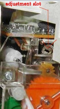
The speed calibration is adjustable by means of a 'potentiometer', a word that means a rotary electronic rheostat, in this instance a quite small one. It is located on the side away from the odometer stepper coil, towards the lamps ...just above the yellow plastic gear, and if the speedometer unit is not separated from the rest, it won't be seen. It is behind the gears that drive the odometer, on the small printed circuit board ...that the 3 pin connector plugs into. Here is a photo, identifying the small slot in the potentiometer:
Here is a link to an article about a software program used with a laptop computer, etc., regarding calibrating the speedometer for any tire size, etc. You really have to dig into this to understand it. Even so, it is way over the top on what YOU need to do. I suggest that the things in this Link are way too complicated for your needs. My method is vastly easier.
http://www.k100-forum.com/t2038-karamba-speedometer-calibration-program-tutorial?highlight=karamba
How to go about calibrating the speedometer yourself:
Rotating the adjustment COUNTER-clockwise will make the speedometer read slower. There is a single black screw on the back of the speedometer that attaches it to a plastic arm, reaching from the center carrier. Remove that screw, and the speedometer can be moved forward to access the potentiometer. Lift away the subassembly, exposing the adjustment screw. Reconnect, power up the ignition, and apply the described magnetic field to the pickup at the rear wheel, and adjust the potentiometer at right side edge of the PC on the speedometer subassembly.
My procedure works easily and well. You can simply travel down a straight road using a GPS. Read the speedometer, and read the GPS. When back at your garage, remove the instrument pod and make the necessary adjustment, but do follow my very specific instructions, so your amount of time to get good accuracy is minimized. A GPS makes things much easier, although you certainly can use road mileage markers and a watch. I recommend the GPS. Since you can simply turn the potentiometer adjustment a small amount, then go for another riding test with the GPS, that is one method. You already have been told which way to turn the potentiometer. I am going to include more information, so you can use it if you wish.
A bit of background information:
The Classic K bikes do not use a mechanical cable for the speedometer drive. Inside the rear drive there is a toothed wheel. A magnetic pickup device (sensor) plugs into the rear drive and is positioned close to the toothed wheel. Every time a tooth passes the magnetic pickup sensor, a tiny electrical pulse signal is developed which is sent via wires to the instrument pod, where electronics processes that signal by the number of pulses in a given time period, and then applies the result to a pulse drive motor, that powers the speedometer indication needle. The circuitry for both the speedometer and odometer are on the internal circuit board, and the internal electronics is complicated, but you need only to know that the speed reading section has an adjustment, and you can adjust it. It is common for the adjustment to be factory set to purposely read high. You will find the odometer reads accurately for the stock size tires, however.
It is possible for you to apply a magnetic field to the outside of the rear drive, which energizes the sensor. With the ignition ON, the speedometer will read out something. If you know the various relationships, you can determine the accuracy immediately. My method will avoid you making any tire measurements, considering weight on the tire to get true diameter,..and...well, eliminate a lot of other time-consuming and complicating 'stuff'. You don't have to do this magnetic field stuff, but it can save you time; and, you gain knowledge.
Information on the magnetic field needed, how to produce it, etc:
1. Use a common soldering gun, of the type that has a transformer, which produces a large magnetic field and is powered by your 120 volt wall socket. Turn on the motorcycle ignition. Bring the soldering gun body, trigger depressed, near the rear drive pickup (not too close). As you bring the energized soldering gun towards the rear drive, the speedometer needle will suddenly move, and you need only to move the soldering gun close enough for a solid stable reading. Since the power line is a VERY accurate 60 Hz in the USA; for a stock tire size, it just so works out that the speedometer should read exactly 45 mph. NOTE that while this should be close to perfect on what YOUR speedometer indicates, it might not be. Re-adjust the potentiometer for 45 mph. Stock rear tire size is assumed here. Another way of how to do this might be to travel at 45 mph indicated on a GPS, and note the error on the speedometer (any tire size for this test). Back at your garage, use the magnetic field source, and adjust the potentiometer to correct the error on a miles or percentage basis, turning the potentiometer in the correct direction. You can do it the other way too, ride at an indicated, on speedometer, of 45 mph, then read the GPS, then adjust/compensate.
If you don't have a transformer type soldering gun, you can also use a large powerful power-line operated de-magnetizer, etc. If you are in a 50 Hz country, or a country with Kilometer readings, simply make a simple ratio conversion, and convert to Kph if needed for your speedometer (many speedometers have dials calibrated in both, so no calculation may be needed).
You also can fashion some sort of magnetic field device from a modified bell-ringing transformer, or just use a super-strong old-fashioned magnetic tape eraser (See my SALE page); or, other means. Often a small 120 volt transformer used normally to power such as a high intensity lamp, etc., will work fine, even with the lamp in it. Try it near the rear drive sensor point, ignition ON. If it does not make the speedometer needle move; then, if not needed for anything else, try removing the laminations such that the laminations end up being a U or T configuration, and not completely surrounding the coil. Since the magnetic field producing device need only be turned on for a few seconds at a time, you have a wide leeway in what type of devices to use; since even higher power devices need only be on a short time, and overheating should not a problem.
Using the 60 or 50 Hz line powered magnetic field method of getting an indication on the speedometer, together with a GPS, will give you a relatively easy way to calibrate the speedometer for ANY tire size. If you do NOT use the magnetic field method, then you likely would be using the GPS method. The only problem with THAT method is that it likely will take several 'tries'; each time making a small adjustment to the potentiometer in the pod. However, it does work well. Road mileage marker method and a watch can be used too, of course. I've tried that method, and have found errors, so if using that method, perhaps do several miles of markers.
2. Another method is to make up some sort of solenoid with enough turns that an audio amplifier can drive it without injuring the amplifier. Place the magnetic field near the rear drive speedometer pickup. With the ignition ON, notice the speedometer effect. You need a very accurate audio oscillator to drive the audio amplifier. This method allows you to check the accuracy at any reading of the speedometer (such as 120 Hz being 90 mph). I suggest that unless you are very nerdy, with access to an audio oscillator and an amplifier of sufficient power, and an electronic frequency counter, that you avoid doing it this way. NOTE, again, this is for the STOCK tire, but you can do calculations for any size tire diameter.
Checking the speedometer against a GPS on a straight road will provide checked accuracy, as it eliminates any tire effects, theoretical values effects, etc. You can also do your checks at various speeds.
3. NERDY: The electronics inside the instrument pod is factory set by circuit arrangement for a 'divide by 64' function for electrical signals from the sensor input from the rear wheel (6 tooth pulse wheel). It is possible to determine, from tire size, the pulses per mile: (64)(pulses per mile) = xxx pulses per mile from the rear wheel. Multiply YOUR xxx value by 1/3600, and this equals pulses per second per each mile per hour. I suggest you forget about any thoughts of doing anything with this information....as well as this next little bit: One could also measure the rear wheel rolling distance. The rotor in the rear wheel has SIX teeth...so one could calculate the number of pulses per so many feet and inches. Go to the following site and to the Instrument Cluster section. You will find several articles about calibrating. https://ibmwr.org/index.php/k-bike-tech-articles/
4. If you have a sidecar rig, and are using quite small car tires, you might not have enough range on the potentiometer to make the speedometer read correctly. If not, you will need to change the value of a resistor connected to the potentiometer, which is, stock, 33K ohm. I have had no problem with 14" and 15" tire sizes and NOT changing the resistor.
There is NO easy way to adjust the ODOMETER. There is NO adjustment in the instrument pod. There IS an electronics 'box' available on the market that can convert the rear signal to a signal that works both speedometer and odometer accurately, but it is pricey. Only those who have made a VERY MAJOR change in tire diameter, should even consider such a method; after all, the speedometer can be adjusted as shown in this article, and the odometer will simply read too fast, if a smaller tire is installed. To give you an idea, when I changed to a 165/70 rear tire on a 14" rim on the K1100LT, I had no problems adjusting for an accurate speedometer, but the odometer read ~12% fast.
5. Especially nerdy: If you want to go so far as to make a cable up, so you can do calibration checks/adjustment, and more, for the K instrument pod, even on the workbench, and use a laptop computer, and a software program that is quite nice ....then... read this entire article, maybe a dozen times for understanding:
http://www.k100-forum.com/t2038-karamba-speedometer-calibration-program-tutorial?highlight=karamba
Clock:
The clock is normally 24 hour. It is possible to modify the circuit so it reads in 12 hour time. The modification is simple.
https://ibmwr.org/index.php/k-bike-tech-articles/
The ideal time to do this modification is probably when you are recalibrating the speedometer.
Resetting the radio code:
To set the indicator ON, turn off the power and press and hold the band switch. The numbers will disappear. Re-enter the code.
If you made a mistake, hold the band switch again, then re-enter the proper code.
To clear the indicator, turn off the radio and press and HOLD the band switch until the light/numbers goes out. If this does not work for you, try doing the same with the ST switch.
SOME of these radios work a bit weirdly on the code setting.
Revisions:
02/08/2008: Add hyperlinks at top of page.
04/26/2010: Ibmr.org links NLW, so used generic homepage link and added notes.
10/08/2012: Add QR code, add language button, update Google Ad-Sense code; simplify the article, yet add clearer better information & procedures.
04/24/2013: Add 8; re-arrange for 9 from a separate heading.
10/04/2014: Clean up article so is much more neatly presented, use of tabs, indentations, table.
03/13/2015: Remove some sections, simplify some areas, expand others.
08/18/2016: Update Clock 24>12 hour link; update metacodes, H.L., scripts, fonts, colors, layout.
07/30/2017: Eastern Beaver has again changed locations in its website. I removed the two 404 not found links, and substituted the main page link.
02/10/2018:
Reduce html, fonts, colors. Add 10pxl margins. Re-arrange much of the article. Clarify some details. Still kind of messssy!
� Copyright 2020, R. Fleischer
Return to Technical Articles LIST Page
Last check/edit: Sunday, December 13, 2020