
|
|
The advertisements above are Google-sponsored. These
support the testing I do. Thank you for clicking on them at
every visit, and for your donations! The Donating article
extensively explains this website's history, philosophy, and
operations.
K-hints
for classic K bikes; K1, K75, K100, K1100
� Copyright 2020, R. Fleischer
https://bmwmotorcycletech.info/K-hints.htm
K2
1. Side-stand switch: Many a K bike owner has had problems with the sidestand switch. The switch is in the circuit for the fuel pump relay coil, and if the switch is not electrically closed, the fuel pump will not operate. Those of us with sidecar rigs simply remove the switch and join the wires. On a K11, the side-stand switch is S9093 on BMW schematics. It is NOT found on the frame diagram, but on the engine circuit diagram, as Seitenst�tzenschalter. BMW makes the switch with its wire and plug as one removable assembly. That plug fits into its mating plug found on the RIGHT side of the frame not far from the computer and battery, and it has a green-yellow wire and a green-red wire. Cut the plug, join those two wires neatly, use shrink tubing over them. Keep in mind that if you bypass the switch, you eliminated a safety item. I make no recommendations. DO NOT ride off with the side-stand down!!
2. BMU: The K bike incorporates a lot of electronics besides the ABS computer, instrument pod, & Jetronic or Motronic computer. One such item is the Bulb (lamp) Monitoring Unit, which may be called a 'relay' on schematic legends. We usually call it the BMU. BMW calls it lampencontrollgeraet. In the majority of the instances of a failure of this bulb monitoring relay box, it typically shows itself by intermittent or no lamp power. The problems are poor solder joints on the BMU model with the reed relays version, on the soldering side of the printed circuit board, whether or not you have a modified lamps system. If you have added any incandescent lamps to existing lamps circuitry, the additional lamps may draw a fair amount of current, and will tend to heat up the BMU solder joints even more. Further down this article is information on how to resolder the reed-relay version of the BMU, not as easy as it sounds.
If the ABS warning light will illuminate (bulb is known good) and do such as turning off after reaching the minimum speed, .....but the other 'general' red warning light is staying on ...or some strange combination of these two warning lamps ...the BMU may be at fault, but there are two other common possibilities. These bikes need silver color base metal type lamps. Do not use 'American' or other lamps with brass colored bases. Clean the bases of all lamps, I use very fine steel wool or quite fine grit sandpaper ... and then put a very faint coating, really just a wipe of a tiny tiny amount, of Caig DeOxit, or similar protectant on them and the contact(s). Be sure the bulb and socket contacts look to be in shiny & good condition, and that the socket contacts have spring pressure behind them.
Another rather common problem is that both front and rear brake light switches must be operational, or a fault may be registered and the red light will come on, and stay on. If you do not first activate both brakes; or, if one or both switches are faulty; the warning light will not extinguish.
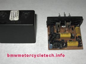
Description of this Bulb Monitoring relay unit (BMU):
This 'black box relay' includes timers, I.C. chip (1 on early versions; 2 on later versions), and lots of parts, including 3 reed relays in the early version. Both versions look the same on the outside; and have the same part number on the outside of the case (on the top). The ones I have seen all had a number 61.13-1 459 003 molded into the top of the case. Only (usually) the early version with the three reed relays gives problems ....and is fixable! ...and you will want to, because the relay box is expensive! The BMW number is 61 31 1 459 003 ...notice how it is close to the number on the relay. Last time I checked, that relay was $250.00 or so!
This unit is complicated in operation. The internals of the bulb monitoring relay unit has the various lamps such as the running and brakes lamps passing their current through either a coil on a reed relay, or through a thin band of metal on the later models. On the reed relays version, which is the version that usually gives trouble, note that I said that the current passes through the reed relay COIL. This is a bit simplified, as there are three relays and there is a current flow under certain conditions through one reed switch. The magnetic field created by the current in their coils is what actuates the internal reed contacts inside those reed relays. BTW...the reed portion is very tiny, hidden inside. The reed relays are configured so that total lamp current for that particular reed relay must exist in roughly the proper amount, or the dash pod lamp will indicate a fault. This particular function is quite tricky in how the reed relays circuitry is designed. In the same complicated manner, the brake monitoring reed relay is set up to monitor and respond to first use of both front and rear brakes, before extinguishing the lamp in the instrument pod (delta symbol, red). Yes, complicated, plus the timers and other functions.
If the brake lamp current is too low (lamp burned-out, or an LED substituted) the delta dash lamp will be illuminated, and will not be turned off by the use of the front and rear brake. Adding lamps that draw considerable current (incandescent lamps) will possibly overheat the lousy factory soldering job at the reed relay connections. Re-soldering them PROPERLY, as I note, below, will usually fix the problems. I have seen bad solder joints at those reed relays even with the stock lamps.
The addition/substitution of LED type lamps (for such as running lamps) can cause the BMU to act up; even though the extra current drain is quite small. It is not the low current drain, it is far more complex, as an LED is, after all, a type of diode. Addition of incandescent lamps usually causes malfunction or display of the problem light output of the BMU strictly from the too-high current.
The BMU box, upon seeing a fault, causes illumination of the red delta symbol dash lamp & the the ABS and BMU send faults output to the same 'delta' lamp. The ABS has another lamp in the instrument pod, not talking about that one here.
In normal operation, application of both brakes, simultaneously or one after the other, turns the warning lamp off after any self-checks.
If the rider fails to manually turn off the turn signals (called trafficators in U.K.) after a certain number of feet of travel or time, then turning off the turn signals is done by a combination function of the flasher relay & hazard circuit & the bulb monitor unit, ....while it has an interconnection, it is not a direct function of the BMU. Automatic shut-off of turn signals is had after either/both time & distance. That electrical signal comes from the speedometer/tachometer circuitry in the instrument pod. The specification is 10 seconds above 30 mph, or 690 feet (210m) in slow traffic.
There is a fuse, 15A rated, it is 2nd from top fuse (F2).
If a rear run or brake lamp burns out, the center delta warning symbol instrument pod lamp is supposed to illuminate to warn you of a bad lamp.
There is an additional ABS lamp in the instrument pod, & the circuitry of these two lamps, the ABS lamp & the Delta warning lamp, interact. You also have a ABS cancel (bypass) dash switch that is in the circuitry. That lamp/ABS/switch wiring and circuitry is such that a true fault will cause the lamp to re-illuminate regularly, even after using the cancel switch (to remind you to fix the ABS brakes, or whatever is wrong).
If you have gotten the idea that the electrics for just lamps and a few functions are way overly complicated in your BMW bike, you are certainly correct. However, requirements of various Countries has made it mandatory in many instances, and BMW has also incorporated additional functions. There is a saying, paraphrasing here, that if BMW can make it more complicated, it will.
A mini-summary here is ......those with enough (or too little!) lamp loads may well have problems with the bulb monitoring unit (besides the solder joint problems). The bulb monitoring relay unit is a costly item. It gets complicated if you try to use LED lamps instead of normal drain lamps. I do not recommend use of only LED lamps (as in replacing incandescent lamps); but will outline some uses & problems & fixes. In some K bikes, just adding low to modest drain LED lamps will confuse the BMU, due to DIODE effects, rather than current drain.
I have information in this section, below, on what is going on, and how to solve the bulb monitor indication problem, well, with caveats. I do not recommend adding high drain lamps, without being prepared for re-soldering the reed relay connections inside this bulb monitoring box. It is possible that soldering problems would be much less likely on the NON-reed-relay version, but I have not tested for that. I will get into various things about the BMU in the following sections.
You can remove the bulb monitoring unit, save it with your BMW shelf items. You will need to make up short jumpers. These are, EACH, just short jumper wires with male spade connectors on each end. You will simply be, in-effect, jumpering certain wires that already are connected to female connectors in the socket that the BMU was removed from. Push these male spades of your made-up jumpers into the appropriate socket places corresponding to the wire colors for that socket.
Jumper the gray-red (this is from the handbrake lever switch for the front disc brakes) & the gray-green (this is from the foot brake switch) to the gray-yellow (this goes to the BRAKE LIGHT). This requires a THREE male spade jumper be made up.
Jumper the green-black (may be white-black)(this connection wire goes to fuse F2, which is supplied power via the ignition switch) to the gray-black (this is to the rear running light).
Result of the above jumpering should work on all Classic K-bikes. Depending on the bike, your BMU no longer monitors the rear running and rear brake lamps (because you removed it, and then added the jumpers so the lights would work). In addition, monitoring will no longer operate the hazard and ABS fault lamps, etc., in some circumstances. This should not be of any real problem; at least it never has been, for me. I DO check that my lamps work by a visual look-see! Remember how older motorcycles with no bulb monitoring, etc., all worked! .....yep, back to that.
There is another way to bypass some of the bulb monitoring relay functions, and I will show two versions below. In both these two methods, the BMU unit is left plugged-in, after its modification. NOTE that these mods are for the REED relays type units ONLY, as I have not yet found any need; nor request, to do it for the non-reed relay version.
Method #1; basic bypassing of the BMU; the BMU is left in place on the motorcycle:
You will be bypassing ONE of the internal reed relays, and then the dash instruments lamp will work properly-enough, but you won't get monitoring function on the RUNNING lamp(s). If you do this modification, the delta symbol lamp will properly illuminate upon the ignition being turned ON, and will be extinguished after use of BOTH front brake and rear brake....one before the other in either order, or, together. You can do this with the battery still connected:
Lift REAR of fuel tank rather high, for access to relay box & remove the box cover. Do NOT strain the wire from the pump, etc, as you lift the tank; disconnect things as needed. Use a block of wood under the tank to keep it high. The BMU black box under discussion is against the middle of left side of relay box. Unscrew & remove the single 8 mm hex metal-screw holding the relay unit to the relay box. You can now unplug the BMU relay from its socket & remove the relay to the workbench.
At the base of the relay, first along one short side & then the other, pry with a sharp small thin screwdriver or other tool, until the base of the relay with its connection prongs is released from the black cover. Be careful not to stick the tool in too far. NOTICE how the printed circuit board fits into the case in ONE direction only; there are ridges molded into the case. You will want to replace it properly later.
With innards exposed, see three yellow-wrapped reed relay units probably marked CLARE CUP S 10008. No reed relays?... then you have the later BMU and I have not prepared instructions for you. Yes for the relays?....>>>The initial one you will work on is in the middle of the printed circuit board. You will be adding a jumper wire. The smaller photo, on the left, is of the case & the jumper, hard to see, being done from the top. I had to scrape-away a coating to do this, & this is the first one I ever did, but I recommend I you do all jumpering from the bottom, as in the larger photo, which identifies this basic jumper. The rest of the instructions follow after the photos.
Below, shown with uninsulated wires, which is OK as used, above the PC.
You may want to use insulated wires.
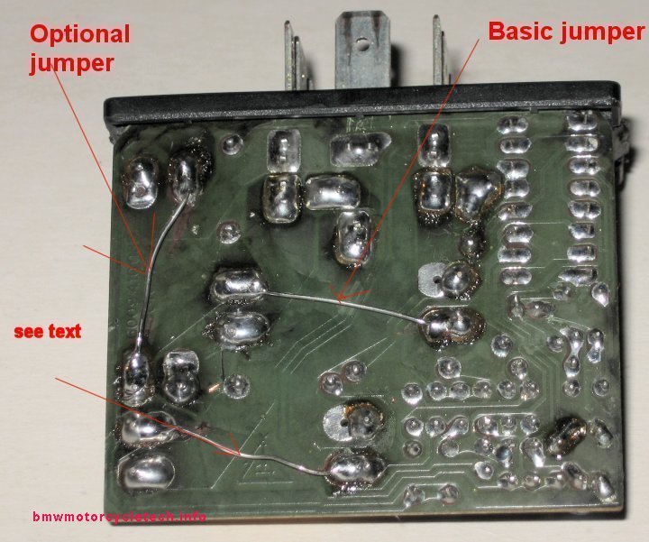
Do the basic jumpering of Method #1.
Do two additional jumperings. These optional jumpers are not described here as to complex functions, but I recommend you do them; particularly if you have a sidecar rig with added incandescent lamps.
READ THIS SECTION, even if NOT doing either method #1 or method #2, no jumpering or other modifications inside this REED relay type BMU:
Carefully examine the printed foil side of the board. Use a strong magnifying lens. You may find bad solder joints, even cracks. fix them, and do it carefully. It is rather difficult to properly solder to the reed relay posts on the printed circuit side of the board (two posts at each end of each relay). That is due to the type of relay post metal. Carefully scrape the relay post metal with a sharp edge of an Xacto knife or other tool, to very clean and shiny condition. Use acid-core solder. I am aware of the potential problems with acid-core solders, which is not important here! You must use a quite hot soldering iron, preferably with a tip assembly that is fairly massive. The soldering iron need not be overly high in wattage, even a 25 watt one with a large tip MASS is adequate. After soldering, CLEAN the re-soldered joints, with home-type iso-propyl alcohol. In the majority of instances of failure of the BMU, the problems are poor solder joints at the reed relays on the soldering side of the printed circuit board, whether or not you have a modified lamps system. The connection prongs (stiff wires) of the reed relays are made of a metal that is NOT easy to solder. I have seen many a factory soldering job that is poor here. The various stock lamps draw enough current that the solder connection overheats and fails. This is especially so if you have extra lamps. I use a 10x eye loupe to look at the solder joints. If the joint is poorly soldered, cracked, broken, or questionable, re-solder it.
Here is more on how to do it:When you are finished soldering, clean with Q-tips and alcohol, and inspect with the 10X eye loupe loupe again. The solder joint must be 100%. If you have it available, plumbers 50-50 solder, used with rosin as the flux, will make for a joint that will hold up to heat a bit better ....but might well not solder as well as acid-core solder. Because of that, I use the acid core solder first, then clean, then re-solder with plumbers 50-50 (with rosin flux). I SUGGEST YOU INSPECT EVERY SOLDER JOINT ON THE ENTIRE BOARD, FOR CRACKS, USING A STRONG MAGNIFYING LENS. Use a strong light, and tilt the board one way, then another, so to eliminate tiny shadows and reflections. DO NOT use acid-core solder on anything but the reed relay short stubby wires on the soldering side of the board. The reason for being so persnickety about all this soldering business is that even with only the stock incandescent lamps the current flow through the solder joints is fairly high for the solder-interface. Properly cleaned/abraded/soldered, the joints will NOT fail, even with 50% more lamp load than stock.
Reassemble the relay into its black box. Mentioned previously is that the electronics board fits PROPERLY only one way into its black box (there is a slot for it). Connect the socket to the relay and install the relay with the 8 mm hexhead holdown screw, which need not be too tight, it only holds this plastic relay. Test the functions with the key switch ON. You should have a rear running light. The rear brake light should light up if the front brake lever is pulled backwards or rear brake lever is pushed. Pushing both, either together or one at a time, should extinguish any warning lamp. If you have ABS, and depending on the optional jumper, etc., you may or may not have normal ABS lamp indication in the DELTA LAMP. Bulb monitoring may be defeated. NOT defeated is the time and distance shut-off off the turn signals.
I have NOT YET modified a later relay, of the type with three metal strips inside and no reed relays. These BMU's don't seem to fail much. Those metal strips seem to be VERY low ohm resistors. I think one or more can be replaced, if needed with a simple piece of copper wire ...I have NOT YET tried that!
Adding in the "flasher" unit to the discussion of the BMU, etc:
The FLASHER lamp unit is LOAD sensitive, and if you substitute a LED, single or array for even one lamp, it will flash rather fast, & while this is cured by adding a parallel resistor, the resistor uses a lot of watts and adding one defeats one of the purposes of using an LED unit, which is much lower current drain. That's really not a great argument for changing to LED lamps, as the K bike has LOTS of alternator power. A standard incandescent lamp produces better light output, in all directions, than most all LED conversion lamps. Conversion to LED lamps does offer very long lamp life, and if done properly you can add several LED lamps or lamp assemblies, etc.
Owners often modify the turn signal lamp sockets for dual functions, such as adding a running lamp function to the turning lamp function; or, adding braking lamp function. Perhaps the front turn signals lamps sockets are modified for running and turning. I consider that type of conversion to not be good, because you really do want the front turn signals to stand-out strongly to oncoming traffic. But, I do provide information, and combination High Brightness LED lamps in the common #1157 bulb package can work for this. I recommend the EURO lamps, not the 1157. See my https://bmwmotorcycletech.info/lamps.htm article and a few paragraphs later in the article you are now reading. NOTE that silver base lamps are more reliable for connection, than brass base types.
For the FRONT, the stock plastic amber lenses and reflectors have characteristics that are not good for dual function LED lamps, even the types with multiple super-bright LED's (no matter if white light or amber light LEDs) (and even those that have extra LED's pointing sideways). These are made in "1157" types and similar, that include extra brightness for turn functions, and my comments are the same. I DO NOT recommend modifying for LED lamps for the FRONT turn signal housings for 1 particular reason (out of perhaps 3): the unmodified lens/reflector BRILLIANCE DIFFERENCE between run and turning is not great; and you do need oncoming traffic to really see that your lamps are flashing. Still, it can be done with a bit of work on the reflector, and then is reasonably OK. I suggest the same cautions,.... at least you should SEE (pun intended) if my comments apply, for any proposed REAR run/brake function. I recommend using common 1157 or similar incandescent lamps, in silver base or equivalent for those twin functions, as its brake (or turn) section of the lamp is VERY much brighter compared to the LED units that are supposed to substitute for a #1157 lamp. Yes, I am including the LED types that have many small bright LED's in them, with some sideways.
For those with more curiosity, I have a lamps article, which discusses all lamps in depth:
https://bmwmotorcycletech.info/lamps.htm
Here is a snippet about the '1157' size lamps, from that article:
If you are thinking of modifying the existing turn signal housings for dual-function, you may be interested in reading this article:
https://bmwmotorcycletech.info/addingrunninglamps.htm
I wrote that article specifically for Airhead conversions, but you will find the information useful for other bikes. You can also consider using LED arrays.
ENOUGH about BMU's, flashers, LED's, etc! .....>>back to more K bike hints:
3. Inspect the clutch lever behind the transmission. Road water and grime tends to get into its pivot/pin area and cause wear. The arm rotates on a pair of needle rollers assemblies, and water in there is not nice. Consider removing the lever and drilling, grooving, and tapping, for a grease zerk in the flat area, and cross drilling to the bore. Do not weaken the shaft and lever.
BMW offers a FORWARD fender extension piece, called a Rear Mudguard Extension, that bolts to existing holes, etc., on the rear fender, to help prevent garbage from collecting on the clutch operating shaft/lever. I still think that the shaft lever should be modified to be greasable with a Zerk, but the forward fender extension is a nice thing to have. The Rear Mudguard Extension fits K1, K100RS 4 Valve, K1100LT, etc. There is a BMW Service Information (SI) on it, #46 046 94 (2650) dated November 1994. The parts you need are: Mudguard 46-63-2-307-459; 2 each oval head screws M5 x 12 # 46-63-2-308-633 (these come with special washers); and 2 each nut holder M5 which is number 65-13-1-372-033. You do NOT have to remove the rear mud guard when installing these things, contrary to the SI. You will find your fender is likely already pre-drilled for the extension. Originally this mod could be done by the dealer under warranty.
4A. Fuel Injector and hoses problems.
If your injectors need cleaning and rebuilding (yes, even the O-ring, etc.), try any of these folks:
https://fuelinjectorconnection.com/
Note the spelling.
RC Engineering 20807 Higgins Court, Torrance, CA 90501 Phone 310-320-2277 Fax 310-782-1346 Probably less than $100 for all the injectors to be cleaned, and including shipping ...and they will come back with new O-rings and a flow report.
For other places, see https://bmwmotorcycletech.info/references.htm ....as I try to keep that article always current with the latest information.
****If you are working on the injectors of your K bike, and need the O-rings, you can get a kit of them for 4 injectors, by asking for same at a BMW car dealership, for BMW 318i O-rings for the injectors.There are several types of fuel injection system hoses used on the BMW K bikes. Check with the on-line sources or your dealership, no need for me to list all the hose numbers for the in and out of the fuel rail, the vacuum, etc. ONE HOSE IS ESPECIALLY CRITICAL! For inside the fuel tank, the hose type is called R-10, which is only important if you are going to NAPA or other autoparts store. From BMW, the correct hose is 16-12-1-180-040.
4B. PROBLEMS:
It used to be that the following things were not all that common, but more likely if the bike had been in storage a long period of time. There have been some reported problems in the last few years, from areas you might not think of. The Fuel Injectors on our bikes are similar to most, and certainly similar to the ones used by GM. Much of this information came from Bob Cerullo of "Motor Magazine", and Bill Studzinski of the GM fuels group (part of the Powertrain division). Years ago, gas hoses inside the fuel tanks were being destroyed by such as gasohol and other additives. That is seen less now, but many of our K bikes have original hoses! ...and it is UNclear if the hose material has been changed by BMW. There have been quite a few FI problems. This is particularly so with alcohol fuels. Around 2003-2005 or maybe it was 2006, there were a LOT of car FI problems and K bike problems were also being seen ...they use the car type injectors and system. The problem was sulfate concentrations in ethanol fuels. Anything over 8 ppm (and certainly if nearing 20 ppm) were causing problems. The sulfates would pass right on through the filters! ...then solidify in the injectors overnight, as the engines cooled off. The standards for fuels were changed, and the problems greatly lessened, so the problems seen back then are mostly gone. The new standards are maximum 4 ppm sulfates. That did not fix the problems from deteriorating hoses, and one such deterioration actually adds liquid plasticizers to the fuel, and the injectors could stick.
Another problem was when people first started using ethanol-laced fuels for the first time. Fuel filters were clogging, from contaminants that USED TO STAY IN THE TANKS. The alcohol acted as a solvent on them. Contaminants were seen from all sorts of container ships, distribution channels, and so on, until the alcohol dissolved the contaminants and minimized them. GM found that the contaminants released when ethanol was used for the first time were MORE of a problem than the sulfates in the older fuels. Because of these various problems, GM, Honda, and Toyota and BMW all got together and specified a new standard for fuels with a very specified detergent type and amounts. The new standard was called Top Tier Detergent Gasoline. Information is at www.toptiergas.com
Unofficial word from manufacturer's & those who actually test fuels, is that MOST gasoline marketers have REDUCED the concentration of detergent additives by up to 50%! This is leading to more FI problems, deposits, etc. In May, 2007, the industry had still not agreed to put proper amounts of detergent in fuels, and I cannot furnish a list of what the various marketers are ACTUALLY doing now. California has special regulations. What I am doing is putting Techron in my fuel every few months, and purchasing Chevron or other Top Tier fuels occasionally. Using a Top Tier fuel is what I suggest.
4C. Gasoline's. Read 4B., above, if you have not done that already.
A little-known fact about Classic K bikes, is that very early ones were designed for LEADED fuels. If you do NOT use leaded fuels in these bikes, then do keep an eye on the valve clearances more often than usually done. BMW modified the bikes so they are OK on UNleaded fuels. The modifications occurred at:
K75: does not apply.
K100: at serial number 0007291
K100RT: at serial number 0024999
K100RS: at serial number 081107
5. Driveshaft repairs, U-joint repairs, modifications, etc.:
Hansens in Medford Oregon.
Brunos in Ontario Canada (Bruno may have retired).
https://www.beemershop.com in California for an interesting aftermarket driveshaft that is repairable and greasable.
https://bmwmotorcycletech.info/references.htm article for more information on driveshafts and U-joints in general.
HINT: The rear drive input spline was 16 teeth through 1985; then became 20 teeth. Thus, the driveshafts must match.
6. The K100 heated grips PROPER switch connections are:
Switch selecting pole: switch pin 2, harness plug 3, black/green wire.
Black wire goes to switch 3, same as plug 2.
Orange wire goes to switch 1, same as plug 1.
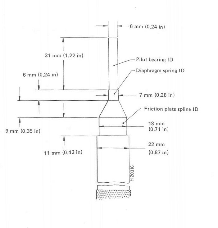
7. When disassembling the clutch, you may or may not find markings, which are used by the factory to space the clutch parts at 120�. Mark your parts!
When reassembling the clutch, if the disc is not centered, the transmission can be difficult to install. The clutch alignment tool is "nice to have" but not absolutely necessary. Before lubricating the transmission input splines, assemble the clutch and tighten the clutch bolts only enough to barely hold the clutch plate in place against gravity. Using your fingers around the outside edges and your eyeballs to get the clutch plate centered as best you can. Slide the transmission on and wiggle it around until the input shaft finds the clutch plate. Rotate the transmission input shaft if you have to (usually only a small amount is needed) by having the transmission in 5th gear and rotating the output. Push the transmission forward all of the way ....and then pull it STRAIGHT back. Then tighten the six clutch bolts to specifications. Recheck that the transmission will install. Lube the transmission input shaft splines. NEVER lube the clutch disc splines.
If you wish to make the clutch disc centering tool, here is a sketch:
8. Rotate the radiator fan by hand a turn or two after a Winter storage period. If you can't reach it, use a long rod, even a wood dowel.
9. If the M/C won't go much faster than ~45-60 mph or so, the switch at the fuel injector rear section, operated by the throttle, could be shorted or jammed, causing fuel to be shut off above around 3000 RPM. The purpose of the switch is to shut off the fuel when the throttle is closed above ~3000 rpm.
10. DO NOT try to start a ABS-equipped K-bike with a poor or relatively discharged battery ...it can cause the starter relay contacts to weld shut. On ABS 2 bikes, it will register a fault in the computer memory.11. The Fuel pump connector and wires go under the tank area to the inside pump and can become problems, with wire breaks and connector corrosion, etc. If the pump does not run, check those things. If the bike sputters to a stop, it may be fuel pressure in the fuel tank. Open the cap, engine running, ignition on: pump running?? If not, check the fuel tank connector behind the RH side panel, then the relay in the housing below the tank, and its fuse. There have been problems with the electrical connector, and the wires as they go into the tank. Other possibilities include the pick-up screen being clogged...you have to remove the pump to see that. A typical problem is that the fuel filter may need replacing ...they DO clog.
12. If the heated grips are on, especially on HIGH, and you see the alternator lamp is faintly illuminated, usually only seen at night, that is normal. The cause is small accumulative voltage drops in the alternator system. If more noticeable, I suggest you clean connections at plugs, etc., to shiny, and that may help. There is a diode installation fix, I recommend you do not do it.
13. Don't sit & warm up the K engine for long periods, even on a cold day. Due to its enrichment sensor, the engine runs rich until warmed fully, so ride off relatively soon. A minute or two warm-up is enough unless below freezing, if so, another minute or three. Ride off gently at first, avoiding large amounts of throttle, especially below 1800 rpm. Avoid using over 4000 rpm. Once the temperature is up a reasonable amount, then use whatever throttle you want.
14. Failure to start can sometimes be traced to a shorted grip, causing #1 fuse to blow; also due to side-stand switch problems on 16V models. The reason the #1 fuse can cause a no-start is because this fuse, which goes to the instruments, also supplies power for the starter switch and clutch switch.
15. Remove the final drive every year... or two at the latest ....and grease the splines. This is especially important on K75 models. I like doing that for ALL Classic K bikes at 20K intervals MAXIMUM. Pull the driveshaft and do the other end too. With Paralever models, be sure to synchronize the U-joints (there is a sketch on this website). On Pre-Paralever models, water sometimes gets into the swing-arm. Usually this is through the joint-face between the final drive and the swing arm. This can end up causing shaft failure, ...even failure of the final drive pinion. I recommend removing the final drive, driveshaft, and greasing the splines. You can use blue Hylomar on the seal joint.
16. Few owners ever remove the ignition module that is mounted near the coils, clean the underside and mounting surface, and then recoat with a thin layer of heat sink compound. I recommend you do this on a scheduled basis. I suggest not over 6 years, but it also depends on your mileage and if mostly short trips.
17. The K bikes vent the fuel tank fumes into the crankcase. You will likely find that modifying the system, using the plastic cup available from BMW for the pipes at the rear of the tank, is a good and better idea. There is a lot more on this on the www.ibmwr.org website.
18. A LOT of labor is involved with cleaning and lubrication of the transmission input splines on Classic K-bikes. Use a good grease. My article #73 has an extensive discussion.
19. The early K bike Y spoke wheels used 8 mm metal valve stems 36-32-1-452-748; around 1987 BMW started using rubber stems, in a 15 mm hole, 36-31-7-653-064.
20. empty on purpose
Rev:
05/12/2007: Add #12. Had been published by me elsewhere's, this is an updated version, and edited for clarity.
11/08/2007: Add #6.
06/28/2008: Update considerably the entire article.
10/25/2009: Clean up article; add item 7 clutch and tool information.
11/25/2009: Final editing; changing numbering too.
01/04/2010: Clean up some unclear areas, enlarge information on the BMU.
02/11/2011: Add inside fuel tank hose part number and cautionary note.
02/27/2011: Fix confusing URL.
06/08/2011: Add another injector cleaning service and details.
10/13/2011: Add 19.
11/16/2011: Modify #19, in favor of reader using article #73, which is now very extensive.
04/09/2012: Add information to #4 and add 20.
08/21/2012: Add 21; add information here and there in existing numbers too.
08/22/2012: Expand #2 in detail, add photo too.
09/04/2012: Begin to work on the bulb monitoring relay and lamps, etc., in my workshop. Make initial changes in part 2 of the above article. I will complete it, add photos, etc., when I have proven the fixes.
09/06/2012: Finish work on the bulb monitoring work. Upload with new photo, etc.
09/07/2012: Road test for automatic turn signal shut-off, OK, see part 2.
09/10/2012: Add link to my adding running lamps article
10/08/2012: Finish updates and the adding of QR code, language button, Google Ad-Sense code update, re-number and combine, etc.
01/27/2013: Re-work the BMU section somewhat, for clarity.
06/15/2013: As above.
11/01/2014: Add OOOOPS note on color codes when jumpering socket for BMU.
08/17/2016: Insert K-clutch-tool.jpg, never had done it, although was a place for it & I had the photo. Justify article to left. Updated meta codes, scripts, H.L., layout, fonts, clarity of explanations, move item 20 into item 11.....ETC. (extensive changes, over-all).
02/08/2018: Clean up article: reduce excessive html, fonts, colors, better layout.
� Copyright 2020, R. Fleischer
Return to Technical Articles LIST Page
Last check/edit: Sunday, December 13, 2020