
|
|
The advertisements above are Google-sponsored. These
support the testing I do. Thank you for clicking on them at
every visit, and for your donations! The Donating article
extensively explains this website's history, philosophy, and
operations.
IGNITION:
|
Timing lights: history, types, designs, uses, internal & external power sources, etc. |
Points (both old camshaft nose type & canister types). Also covered: the pesky rubber seal that goes into the points cavity groove. |
|
Ignition modules; original, changes, updates |
New coil style changes |
|
Information on ignition timing versus piston movement has been moved to item #18 at: https://bmwmotorcycletech.info/formulas.htm |
Dyna & other points boosters |
|
Spark plug suppressor caps; also see: |
Coils: specifications, failure modes, testing |
|
Ignition canisters, repairing, etc. |
Dyna, Boyer & other ignitions |
|
Testing & troubleshooting |
High idling rpm |
|
Hall device sensors |
Rubber seal strip at points cavity, pre-1979 models |
� Copyright 2022, R. Fleischer
https://bmwmotorcycletech.info/Ignition.htm
article #30
There are several major ignition system articles on this website. You are reading article #30. You will not get a complete understanding without reading two others: #28 & #29. #31 & #32 may also be of interest. These various articles will just about completely explain everything about the various ignition's, dual-plugging, single-plugging, sparkplugs, etc. I can also recommend article #52 which covers pinging-detonation.
>>>>ESPECIALLY READ ARTICLE 29...WHICH COVERS A NUMBER OF THINGS, INCLUDING DWELL, IN GREAT DEPTH.>>>>
WHILE I DO LIST 'SOURCES' FOR INFORMATION, PARTS, AND REPAIRS THROUGHOUT THIS ENTIRE ARTICLE, THEY SHOULD NOT BE TAKEN TO MEAN THAT THEY HAVE MY UNCONDITIONAL APPROVAL.
You may wish to see Haynes or Clymers manuals. Be cautious for errors in those manuals. They are only "fair" on ignition items & testing, & certainly NOT good for repairs to the innards.
RECOMMENDED: The CHITECH BMW Electric School Manual, likely still available at $30. The description on the Chitech website is not descriptive-enough for all that is in this manual. Mostly written by super-guru, OAK Okleshen! https://www.crbmw.com/chitech-in-the-beginning/.
For a critique of that manual (and some corrections to mark in pencil in yours): https://bmwmotorcycletech.info/chitechelmnl.htm
In-depth information on spark plugs and their caps: https://bmwmotorcycletech.info/sparkplugs.htm
ALL ABOUT TIMING LIGHTS:
Many decades ago, timing lights consisted of a glass bulb containing two separated thin plates or short curled wires, or, whatever, and the glass bulb was usually filled with neon gas. Coming out of that electrically insulated bulb assembly was two high voltage insulated wires, of which one was attached to the spark plug & the other wire was attached to engine ground (case metal). This type worked fine, needed no power from a battery; but, was not very bright. It was OK for a darkened garage or engine area. There have been folks who use this method to light-up a small fluorescent lamp. These methods are all obsolete, although they do work. A lot of old-time mechanics more than occasionally got electric shocks using these methods. Getting an electrical shock from more modern ignition systems is quite dangerous, another reason for use of modern timing lights. I'll get into much more depth on various timing lights just below.
The next timing light development...and this is still from long ago... had a car radio 'vibrator' (vibrating electrical contacts) and a small transformer. The vehicle battery was used to power the vibrator, which produced a truly funky alternating current as needed for input to the transformer. The transformer output was high voltage, which was rectified to D.C. and then applied to contacts inside a smallish glass 'flash tube' that contained a pressurized gas. Sealed into each end of this flash tube was a stub wire. The high voltage circuit included a fairly powerful capacitor that could supply sudden very short time period amounts (tiny fractions of a second) of high current and voltage repetitively, to supply the flash tube power. Triggering of the flash tube was obtained in various ways, typically a few turns of thin wire was wrapped around the glass outside to which high voltage from the spark plug connection was applied to create a strong electric field which enabled the discharge of a fair amount of electric current, but of very short time length, the result of which was a bright burst of white light. Each spark plug firing caused the power supply, with its capacitor, to discharge into the lamp. Note that this type of timing light, as is today's type, was in the shape of a large hand-gun, and had a trigger button that turned the power on and off. This type of strobe light was usable in moderate sunlight due to its much higher brightness, but it still used high voltage from the spark plug connection, although some were sold that used a wire wrapped around the spark plug cable. That got utilized in a better way, in the next generation, information of which follows.
The next improvement had internal transistorized oscillators instead of the occasionally troublesome vibrator which slowly aged to poor performance. The transistorized ones were more reliable, and most had very bright outputs, some even had lense focusability. Some were still shock hazard instruments.
The next improvement was pretty much the standard type used today. These had NO dangerous direct connection to the spark plug. Instead, an adjustable spring-loaded clamp sensor probe unit simply fit over the spark plug insulated wire, and the electric field was sensed by the probe unit, amplified, and triggered the transistorized flash tube circuitry pretty much similar to the previous version of strobe lights. No high voltage connection to the spark plug wiring was required, just the spring-loaded opening 'clamp probe', that contained a coil of wire or other sensor means, to trigger the transistor amplifier, which, in turn, triggered the lamp discharge. The result was a safe and very convenient tool for shop and home, with just about no chance of an electrical shock, unless the spark plug cable wire was very deteriorated. The efficiency of some of these was good enough to allow an INternal battery source. The glass flash tube, nearly the same as previously, produced a short intensely bright white light for each spark plug spark event. The design and circuitry can be made so that the flashing is both reliable & very bright, even at high rpm. This type is still the most common.
Variations include popular types that have a rotary dial, in which degrees of advance or retard for the strobe light output can be dialed-in for special purposes. The adjustment causes the light output to be retarded or advanced, relative to the spark electrical field from the spark plug wire clamp probe sensor, and the amount of such retard or advance could be set by a dial knob. This type can be confusing, and I do not recommend its use, unless you already have one & know how to use it; or, will learn to do so if you purchase one. This type is absolutely not needed for Airheads use, and that includes stock single plug ignition as well as dual plugging; and, AFAIK, not needed for any aftermarket ignition. If you are purchasing a timing light, and are the more nerdy type, you might want the type with a dial for timing degrees setting. While all these common types of strobe lights are pretty much the same (with or without the set-timing dial control), there are some that are more rugged, feel better in your hand & some run off internal batteries instead of the vehicle battery, and many have glass lenses at the nose to concentrate the light or focus the light better. Some have a substantially brighter light output than others.
Variations on the timing dial type are versions that will enable dwell time to be measured or displayed. Dwell time is, put simply, the number of rotational degrees (of 360) during which the ignition coil is being magnetically charged from electrical input, compared to the number of degrees of time of not-being-charged. Contrary to some beliefs and statements, dwell time measurements are not very important to BMW Airhead ignition, any advice to the contrary is not based on facts. Dwell time is more important on engines with one or two coils AND many cylinders, because the longer the dwell time, the better the coil charge, particularly if RPM rises quite high. There is no way a BMW Airhead engine will have a problem with the normally used coils, even at 7500 RPM. The control over dwell period is the points opening; or, if no points, the mechanism that produces the ignition signal ...and, in a few instances ...the electronics modules that may have dwell circuitry. Dwell period time problems with points or points rubbing block wear is possible, and use of too small points gap settings will lead to problems.
Timing light power sources (internal battery or external battery or the vehicle battery):
Timing lights are available that do not need external power sources, that means that the timing light needs no connection to the vehicle battery, but uses an internal battery, usually rechargeable. These can have a possible advantage besides not needing the vehicle battery or an external battery. In rather rare situations, using the vehicle battery to power the timing light (and the ignition of a rotating engine) can cause irregular timing indications. Usually this is in a system with a poor (higher internal resistance) battery, or other fault, so low value engine ignition pulses are seen at the battery terminals which would otherwise be powering the timing light. Some mechanics use a standard timing light that uses external power, that means they use another battery, not the vehicle battery, for power. I have had to do this myself on quite rare occasions. In every instance, the problem occurred (again, it is rare), with electronic ignitions.
In most instances, with most timing light models, one uses, for convenience, the vehicle battery for timing light power. An extremely rare instance is when the timing light itself produces electrical noises, upsetting the timing reading. Less rare but I still consider it quite rare, is when some other problem exists in the vehicle causing strange timing light indications at the flywheel (called the clutch carrier on 1981 and later BMW Airhead models). This can be from such as a bad battery; poor connections; or, in some instances just slightly higher connection resistance at some place(s) in the vehicle ...or, there is electrical noise from a poor diode in an alternator diode board, etc. If some form of electrical noise, including delayed ignition impulse noises, feed back to the timing light via its battery connection, the timing light output can be irregular. These possible events are reasons that some mechanics power their timing lights from an external battery (few use internal battery types, although they may become more popular in the future). So ...there is a possible problem with reading the timing marks clearly and accurately, if the timing light is vehicle powered. This can happen, but almost always does not. The possibility is why BMW recommends using an external power source for the timing light. Such an external timing light power source could be almost any 12 volt battery that can power the timing light.
It is relatively common to see somewhat irregular and unstable timing light indications at the flywheel (clutch carrier) timing marks; ....especially at both a low to moderate idle RPM; but also perhaps at high RPM. Since unstable timing marks are usually due to timing chain and guides and sprockets wear, or irregularities at ignition points, if there is any question of accurate timing, I suggest you do try an external battery instead of powering your timing light from the vehicle under test. We professional wrenches often use the stability of indications to suggest problems with parts wear in the timing chest.
More about false timing light 'information':
Any sort of electrical noise at the battery terminals where you have connected the timing light ... can, but does not have to, ...cause false triggering. Some timing lights are much more susceptible to triggering on electrical noise including faulty ignition pulses at the spark plug ignition wire. False triggering can make it more difficult to determine which of multiple images on the flywheel (or clutch carrier) is the correct one. Multiple images on the flywheel are quite common and usually come from irregularities in the bike's own ignition triggering, almost always from jerking-about of the timing chain, and not problems with the timing light. Irregularities in a points drive can be mechanically caused from run-out at the end of the camshaft (especially Airheads up through 1978). The points-in-canister models of 1979-1980 are more stable than the older points-at-end-of-cam models, but the 1979-1980 is less stable than the electronic ignition of 1981 & later. Irregularities with the 1981 and later electronic ignition timing might come from the mechanical drive to the canister (unusual), but it is usually wear at the chain, guide/tensioner and chain sprockets. It is very easy to see the instabilities with a timing light and use of throttle to vary the RPM.
>>>Try an external battery. If any substantial difference, then best to use an external battery with that timing light. NOTE that some timing light ignition 'pickups' have a marking on them to show the direction they should be fitted over the ignition wire. That marking, usually an arrow, almost universally means the arrow points towards the spark plug, NOT THE COIL. Try both directions on your vehicle, see if any difference. I have seen differences due to internal coil winding polarity at the coil terminals, and for other esoteric reasons. Check at both low RPM (such as at idle) and at high rpm, both directions for the probe.
While the best thing is to power a timing light from an external battery, quite frankly I seldom do that myself ...unless I am specifically looking into certain problem situations. Problems are rare with timing lights themselves. Timing light strobes do fail or wear out, usually it is the vibrator and/or tubes or capacitors or a transistor, depending on era.
I suspect that most all of you will use a timing light that triggers via a clamping probe over the insulated ignition wire, and that has no advance/retard dial. It works fine on our Airheads, no matter if single plug, dual-plugged, one coil or two coils, aftermarket or stock ignition.
On an after-market split ignition, such as the separately-cylinders-adjustable Dyna unit used on the early points type motorcycles, you must set the timing for both cylinders individually. Theoretically this produces a more accurate, less jittery ignition timing. In practice, that MAY be true, but usually is fairly modest in effect. It can also mask some of the aging of the chain, sprockets, & guides. However, another way of looking at this is that since each cylinder is separately 'timed', the ignition is more accurate.
Points amplifiers, sometimes called points boosters:
These used to be made by quite a few manufacturers; but, since the now near universal use of electronic ignition, there are few makers (and I know of no commercially available ones with some of the fancy timing circuitry that was available on a very few, long ago). Today, points boosters/amplifiers are made by only a small number of manufacturer's. They will ...or CAN ....GREATLY increase points life. Accel was a popular brand, and Accel still sells high quality ignition coils. Dyna still sells a booster unit that has been popular for a very long time. These are two of the popular makers in the USA, but kits are available from others, and may have some advantages, with ability to handle lower primary ohms coils and possibly produce better sparks and the reliability may be better, particularly, perhaps, in hot engine areas. Still, since all these units contain transistor electronics, I HIGHLY recommend they not be mounted in hot areas, particularly not mounted to hot engine surfaces. See my references article; or, at least the rest of this section:
Points boosters or points amplifiers do NOT boost nor amplify the ignition spark. What they do is to allow the reduction of the points electrical voltage and current, so that the points have, essentially, no electric spark erosion; or, call it no or hardly any, electrical spark wear. A quite small current passes through the points, although most are designed to have enough so that the points continue to make good electrical contact. It is important, with use of these boosters/amplifiers, that the points cavity, or points canister innards area at the points, be clean and totally free of oil (free of even the tiniest amounts as vapor). These boosters/amplifiers have no effect on the life of the points spring, nor, especially, the life of the points rubbing block. If the points cam (and felt on models having a felt) are kept very lightly lubricated, then the rubbing block will last very much longer, and you will not get squeaks and not have to adjust the points gap and timing very often. That is true for use with a points booster/amplifier; or, points without a booster/amplifier.
KITS are available to put together your own points booster/amplifier:
https://store.qkits.com/
http://www.apogeekits.com.
Also, Arcade electronics; and maybe others.
Velleman is probably the actual maker of all those above kits sold by others, using model number 2543. https://www.vellemanusa.com/. Best, perhaps, is to use: https://www.vellemanstore.com/.
If any of the above links are NLA, then do an internet search.
A problem could occur if you have coils that draw more amperes than any of the points booster amplifiers are rated for, typically rated for 4 amperes for the Dyna Booster and most others. Many have used a booster in an overloaded condition, if they are kept reasonably cool. AFAIK the Velleman is also rated at 4 amperes, but the Velleman is available as a kit, with a large heat sink (as opposed to the SEALED Dyna unit)....and, with the heat sink that comes with the Velleman, I think the unit will handle even more amperes if placed in a relatively cool place on the motorcycle; ...someplace under the fuel tank? I think you could also install a more powerful transistor, on a substantial heat sink.
Even with a points booster/amplifier, you MUST keep the points cam faintly lubricated, or it will wear fast, & may even squeak. The points MUST be clean and dry! I suggest you continue to check the points at 5,000 mile intervals, and if you have a booster/amplifer, run a piece of very clean non-glossy paper through the points to clean them of any very faint oil contamination that gets past the points cavity seal.
NEVER open the points manually very much; opening them quite wide might weaken the spring, although this is overblown in some published literature or on-List.
The NON-canister Airheads have points located on the forward (nose) end of the camshaft in a small engine cavity. The lower points screw head is very close to the points spring. If a wrong screw or washer is use, the screw can contact the spring and the points are effectively shorted, and you get no ignition. This is seen now and then right after someone replaces the points and can't understand why the engine will not start.
Every now and then folks replace the outer aluminum cover and don't pay attention to the points wire. It gets crushed. The ignition might get shorted out immediately...or, it could take some heat/cook cycles before the bike fails to start or run OK. The NON-canister models points connection wire goes from the points cavity through a rubber grommet which often gets displaced when working in the area. DO NOT replace the cover until the wire & grommet are in proper position, or you could cut the wire when replacing the cover. You can use a strong adhesive on the grommet to help prevent displacement ...I suggest 3M or Permatex "super-weatherstrip-adhesive". The BMW price for that grommet will help empty your wallet.
Their is a rubber seal-strip (or rubber O-ring, whatever you want to call it), located in the pre-1979 timing chests, in a groove surrounding the points cavity, having had multiple part numbers in the parts fiche. The situation with them can be confusing. The material came in both short strips, and much longer pieces. You should find out which rubber will properly fit. Install a precisely cut length after cleaning the rubber with acetone or MEK. Clean the cavity groove quite well. Put small droplets of cyano-acrylic glue (Crazy Glue, etc.) in the cavity groove, before installing the rubber. You can also use tiny bits of Super Weatherstrip Adhesive. Push the rubber (do clean it with solvent first) a few times into position as needed. Cut with an Xacto knife to fit; press in again, and let sit overnight. Make the cut as precisely as possible, leaving the most minimal end gap you can...so the pressure of installing the outer cover will cause the seal to be 100%. Next day; clean lightly with acetone on a rag a few times, to get any excess glue removed. DO NOT rub with a bar of soap as the next step after the acetone cleaning. DO NOT use soap at all! I smear a VERY SMALL amount of silicone dielectric grease on the surface, using my fingertip, before replacing the outer cover. For the rubber material, 11-14-1-265-394, is supposedly 3.2 mm thick, used until 1974, approximately. Some fiche imply to 1975. Thereafter, and some fiche say for 1976 to 1978, you are to use 11-14-1-262-644, which is supposedly, in some fiche, 4.2 mm. Awhile back, if you were to order either, you would probably will get the -394 size. Maybe. You MAY be able to use a Classic K bike oil filter cover O-ring, which is 11-13-1-460-425, even a used one! Do clean off the oil with acetone. That O-ring is 88 mm x 3 mm in size, and is used on the Classic K bikes which are K1, K75, K100, K1100 ...at the oil filter outer cover. The O-ring is also used at various places in such as a R1200GS, and K1200. You need to check the particular groove in your Airhead, see what fits. When ready to install the outer cover, be careful; watch the installation ...there is a rubber grommet which has a groove that mates with the outer cover ....and you do NOT want to pinch the wire from the points....and, as has been mentioned, also consider using superweatherstrip adhesive on the grommet. Some use home in-wall solid copper wire for the rubber channel, usually used is the type with plastic insulation. If carefully selected for wire gauge or metric size, you can provide a decent sealing. I prefer not to do that, but to use an all-rubber O-ring, as noted.
Cleaning points:
Rotate the engine until the points are closed (they are then pressured by the points spring blade). Next, open them by hand only a very small amount, just enough to slide a piece of paper between the points. Absorbent paper of some sort, but not a linty paper towel. I have used a non-glazed business card or a bit of common printer paper. First put a couple drops of a fast drying solvent on the small piece of paper. Acetone is fine (not wife's oily based acetone). Acetone or other strong fast evaporating solvent on the piece of paper will remove any oil film layer on the points. You do not want to file the points because that will remove some of the special metal layer plated onto them. Points are expensive, so you may decide to file them anyway when they get worn/erroded a fair amount. If you have to file them because there is a pronounced tit and valley on the points, do it only lightly, and use a fine grit points file or thin flat jewelers file. Keep the tool square to the points and do not finger pressure the points much. I have used diamond or carbide grit impregnated METAL fingernail 'boards', and they work fine. DO NOT overdo the filing and don't file at all unless you have to. The points can have a mild tit and valley and still work fine.
Be sure to lightly lubricate the cam felt (no felts in canister points models) ....and lightly lubricate the cam only SLIGHTLY, with any good soft but high temperature rated grease. Check the points every 5,000 miles for gap, clean and refresh the faint amount of cam grease, and check timing. Do not over-lubricate! Remove old grease first. You do not want grease or oil to get into the points gap!
Be sure the points cavity area is clean and dry; pay attention to the rubber grommet and wire as you put the front cover back on the bike. I will assume the seal for the cavity is good & intact. It's a good idea to VERY LIGHTLY coat the surface of that seal with such as silicon grease (dielectric grease at your auto supplies store).
1979-1980 models have the points located in a canister (which, after 1980, do not have the points, but contain the Hall transistor device). There is no wiping felt for the points rubbing block. Do the best you can with teensy rag bits, and soft high temperature lubricant sparingly on the cam.
Ignition points/ATU/etc:
The ATU (Automatic Timing Unit) is discussed, in depth, at
https://bmwmotorcycletech.info/ignitionsingleplug.htm
SEE ALSO, item 5., well below...
ADDITIONAL information, especially about a high rpm idle problem, is treated in this article, a number of paragraphs below.
CONDENSER: An old-time name for an electrical part properly called a capacitor. 0.2 microfarad, typically for points models.
DWELL: This is covered in depth in: https://bmwmotorcycletech.info/ignitionsingleplug.htm
CANISTER POINTS:
Ignition points as used in the Airhead canisters (1979 and 1980 Airheads models):
Unconfirmed data: Bosch GB534 ...as on Mitsubishi Colt (69-80 6 cyl), some VW (Bus to 1972 for instance). The 01-011 VW points may fit the canister (number may be shown as 01011). Those points have a more standard spring tension, use a fiber rubbing block. If you were using very high rpm all the time, racing, or?, you might want 01030 which has a stiffer spring & plastic rubbing block. Volvo, some Toyota, Ford Cortina TD and TF, 6 cyl Falcom XY and XD, ....etc. Old VW points springs may be too weak, and cause floating problems. NOTE: Porsche & some others, used Bosch GB752, which had a slightly higher spring tension, so less tendency to have floating problems at very high RPM, ~red-line area. Do not willy-nilly install those points, because BMW has a stronger spring points unit for the canister ignitions, it solves a problem seen, if rarely, with misfiring at & above 6500 RPM. NOTE my previous mention of problem if the points are opened much too wide. The part number, which was finally adopted for all the canister points models is: 12-11-1-243-969. This item can be differentiated from the softer spring model by the color of the wire insulation, which should not be black, but black with white rings, or white with black rings.
In Europe, BMW made other changes at the same time to this canister, changing the vent hose to a white colored one (12-11-1-243-920), and the cover went to 2 hole mounting.
The 1979 & 1980 Airheads had canisters with points & did not have a felt pad to help keep the points cam lubricated. If the lubrication on these or earlier points cams dries out, the rubbing block & the cam can make loud chirping or squeaking noises. This indicates that the rubbing block is wearing fast; soon the points will have no opening, & the bike will stumble and eventually quit running or be difficult to start. Remove the outer lid (1 or 2 screws) & lubricate the cam sides very sparingly ....with a high temperature grease ...or, real ATU grease from Bosch. Put one drop of a decent oil on the outrigger bearing if the canister model. Note that the points can not be adjusted properly without the outrigger bearing in place. Do not open the points manually beyond what is needed ....doing so may cause them to loose spring tension and you can then have ignition abnormalities at high rpm.
I DO lubricate the canister cam in the 1979-1980 canisters that have points, & I do it very lightly. There is no felt in most if not all point sets for these canisters. Lubricating the cam lightly (you may have to clean it first) certainly extends points life, & is easy to do. More serious work on the canisters requires a difficult disassembly.
NON-canister Points, that means Ignition Points for 1970-1978 Airheads:
BMW has shipped wrongly made Points, made in China. They did that under part number 12-11-1-243-555. The rubbing block is too long & you cannot get proper timing, etc. Can you modify them? ...I don't know. I have suggested the Noris points from such as Beemershop, etc. Noris, of Germany, was an original manufacturer of BMW points. I am fine with you using Noris points. For some time now BMW has been shipping 12-11-1-243-556, which fit & work OK. Check BMW prices and prices from Bob's BMW, and Euromotoelectric, Tom Cutter, Bud Provin, etc. The requirements for lubricating the points cam also exists for these older model bikes, plus the shaft (cam end) also needs lubrication. Do not open the points manually beyond what is needed. These older motorcycles have a felt as part of the points assembly & it should be kept slightly lubricated. Before the 1979 introduction of the canister, Airhead motorcycles all had points ignitions with felts; the felt and cam required lubrication (both on the engine cam's shaft inside the ATU, and the ignition cam outer surface). Since the automatic advance unit was at the cam tip (not buried as in the canisters), the automatic advance unit cleaning and lubrication could be done rather easily; with two types of Bosch greases used, one for the rubbing block, one for the area between automatic advance and cam ....and the shaft.
DO NOT overtighten the nut holding the ATU to the camshaft tip. There should be a waverly locking washer used with the nut.
Rotating the points plate CLOCKWISE in pre-1979 models will retard the spark.
Don't use the coils with the lightning bolt symbol with points without a high power rated booster.
High Idle RPM (usually after warmup, perhaps as high as ~2000RPM; ALSO, excessive advance range:
These are primarily problems with the ATU mechanism in the CANISTER models. It is possible for the older style ATU to have such problems, but cleaning and lubrication and inspecting for slacked springs on them is easy, and does not need a lot of explanation or caution ...except to NOT overtighten the nut at the tip of the cam!
High idling rpm, perhaps slowly worsening (?), is caused by several possible problems. Sometimes there is more than one of these problems at the same time. Excessive advance range will also be dealt with here. Sometimes the problem is in carburetion, also dealt with here.
1. An internally "sticky" automatic timing unit in the ignition canister at the front of the engine. I discuss how to determine if this is the problem and how to fix it, at 7.
Do it yourself, cleaning and lubrication of the ATU: http://gunsmoke.com/motorcycling/r100gs/auto_advance/index.html
Overhaulers are listed considerably down, near the end of this long article, in its own section.
Another group of photos on how to clean and lubricate the ATU: https://www.flickr.com/photos/getproductions/sets/72157644751098893
2. Leaking throttle shafts; hoses/clamps ... and sometimes leaking intake stubs to carburetors. If the carburetors are sagging, easily seen as the hose from the carburetor outlet to the cylinder head is sagging, tightening usually won't fix things. BMW made a change to the hoses on the GS, and some got on other models, and the hose change is a problem. Info in my carburetor articles.
3. Wrongly adjusted carburetors (usually the idle mixture screw).
4. No slack in one or both throttle cables; or, no slack in the top cable on three cable models.
5. Weak or stretched/sacked automatic advance springs. This is not difficult to determine; a visual look-see will show one or more of these conditions:
(a) PRE-1979 models: The springs do not fully bring the advance weights back to engine stopped position. Usually there is a wee bit of play BEFORE the springs expand (if you move the weights manually).
This can also happen to the 1979 to 1995 canister models, but less likely. For them, the easiest method is to remove the tiny elliptical side plate, and look carefully inside, and use a tiny tool of some sort, to see if the weights have fully returned. If they are sacked, you have to disassemble the canister.
(b) The idle timing may vary more than normally.
(c) The timing RANGE is likely OK, but RPM at which maximum timing is reached is much lower than expected; or the range is otherwise incorrect and needs looking into.
Source for automatic advance springs:
https://www.motobins.co.uk
If the RANGE of automatic advance is EXCESSIVE, you may have bad plastic bushings on the ATU unit. Excessive advance range can be described as: you set the ignition to properly have the S mark centered at idle rpm, but find the maximum advance quits advancing at considerably higher than 3000 RPM.
6. Carburetors wrongly assembled, or other problems. This includes leaking domes; leaking throttle shafts (see item 2); parts of the enrichener gasket are pulled inwards; wrongly assembled enrichener discs or lever assemblies; & wrongly stamped L or R (by Bing factory!!) enrichener shafts. Photos of the proper and improper assembly are in my carburetor articles.
7. Perhaps THE most common problem, if the increase in rpm is quite large, such as to 2000 rpm or so, is a sticky automatic advance unit (ATU)...almost always this is in the CANISTER MODELS ...resulting in a high idle speed due to excessive timing advance, typically after a full warm-up of the entire engine. A full warm-up takes at least 10 miles. Usually you must have the engine case hot, not just the cylinders, for this excessive advance to happen.There are several TESTS and THINGS TO KNOW for PROVING that the ATU is at fault for a high idle rpm after full warmup (rare before full warmup):
(a) Make sure that there are no vacuum leaks at the intake rubber hoses. To do this, start the engine, let it idle (OK to be somewhat above idle to keep engine running, if doing it with a cold engine; should not be needed with warm/hot engine), & spray brake cleaner or other spray solvent or even butane/propane, etc., at the intake hoses, both ends of them at both L & R cylinders. NO rpm change should be noted in these tests ...nor the next ones. If there is any RPM or sound changes, tighten the band-clamps at the hoses between carburetors & cylinder heads & re-check. It is possible for a hose to deteriorate and tightening will not help, so replace the hose if that is found. If replacing a hose on a later model Airhead, particularly a GS, but this has been seen on other late models, be SURE the hose has the correct number printed on it ...see my carburetor articles; because BMW made a change I do not agree with.
(b) Next, spray at the throttle shaft linkage area where the throttle shaft exits the carburetor. If the internal throttle shaft O-ring is bad, you will have to disassemble some of the carburetor to replace it.
(c) Make sure that there IS free play in the throttle cables at idle (throttle rotated to off); and, that there is NOT a wrongly adjusted idle mixture screw.
(d) In some instances, just turning off the engine & restarting it after it was already hot & exhibiting the very high idle, provides inertia of starting forces sufficient to 'reset' a stuck ATU ...so try that. If then a normal idle, it IS likely an ATU problem. A few repeats, & if this is the situation, you can be nearly 100% sure it IS the ATU needing attention.
(e) If restarting doesn't show up the problem, then do get a friend's help. First take the bike for a 10-20 mile ride, & if the idle rpm went quite high (~2000..??) after a full warmup of the engine case, then pull the bike up to a nice big solid object, like a brick building wall. You could also just use the brakes. With the bike in first gear, still idling at the high rpm, throttle off, let out the clutch very slowly, which loads the engine, slowing it. Slow it slowly down to ~900 rpm.
Have your friend use a timing light, triggered from a spark cable by clamping the sensor pickup over the cable. It is OK to use the bike's battery for powering the timing light for this test. Have him point the light at the timing hole near the oil dipstick. If the timing is quite well-advanced & not where it should be, which is close to the S mark at this slow idle rpm, then the ATU definitely is the problem. Prove it by pulling in the clutch ...you have a very high idle rpm again, yes? Try several times. If the idle does not go high again, then you may have 'reset' the ATU, and while not mandatory, I think you should do a bit of a ride and then repeat the testing again, to be absolutely sure of the ATU being the problem.
(f) The proper and full fix is to disassemble the canister & clean & re-lubricate it. That is not all that easy for the novice. Sometimes simply removing the oval side plate & squirting in some cleaner &/or a fine oil (not ever WD40, which tends to solidify over time) will help, but may ...or may not ...hold up over time. If doing that, be sure to shake out the excess. When disassembling the canister, some of the ATU parts may need to be burnished (sort of a more complete polishing with a very fine grit sandpaper or silicon carbide paper) which does help. Typically a careful cleaning & polishing by such a very fine paper, finished by light lubrication, is going to fix the problem, permanently. Fine grit means around 1000 grit, but you may have to begin with a bit lower.
(g) You could have slacked or otherwise weakened ATU springs. Easy to test for, use eyeball & the timing light, and look at the springs, through the elliptical side hole.
Source for automatic advance springs:
https://www.motobins.co.uk/
Assuming you have fixed the high rpm problem & all is OK, there are things you should do, besides resetting the canister timing adjustment. Be sure the valves are properly set! Now re-sync the carburetors after a ride or other warmup. During the re-synchronization, pay special attention to the idle mixture screw, idle balance, & ending idle rpm (1000-1100). Many do NOT set the idle mixture screw properly. If not set properly, the idle RPM can vary considerably more than normal from cold, or just barely warmed, to a fully hot engine. Start with the idle mixture screw further out than factory or Bing or other manual such as Haynes or Clymers says initial adjustment should be. An extra one full turn is always enough. From that further out point, slowly screw inwards, until engine rpm and sound peaks & then slowly more until the rpm falls off a bit ....you will hear some engine stumbling and heaviness. Back the idle mixture screw off slightly to the exact peak of rpm and sound. Then back it off an additional 1/8th of a turn (not over 1/4th, and that is usually a bit too much). Go back & forth between the idle mixture and idle speed adjustments until carburetor adjustments are such that no further improvement can be made. The shorting method works very well here, read the article, link below. You must synch the carburetors so the effective rpm on both cylinders is the same, and the effective idle mixture is the same. You cannot do this properly without the shorting method or using an instrument (which is a bit less accurate). If you take more than a few minutes for all this, either ride the bike to cool the engine a bit; or use fans blowing on the cylinders.
This website has an article that describes how to get an appropriate squirrel cage fan for nothing. https://bmwmotorcycletech.info/tools.htm
See the following article for how to adjust carburetors: https://bmwmotorcycletech.info/synchcarbs.htm
A rare, but super-annoying problem to find, ....but a simple fix:
Do you have a BMW electronic ignition Airhead that will idle OK, but won't raise rpm properly? This problem acts somewhat similarly to a hole in one or both carburetor diaphragms.
The actual problem is in the ignition kill switch at the bars. Just cleaning that switch may (or may not) fix the problem. Bypassing the switch will show whether or not the problem is that switch. This fault has perplexed even some senior technicians trying to find the source of the problem. I first ran into this situation long ago, & finally identified it, after a lot of labor. I used an oscilloscope to find the problem. I found that an ohmmeter or voltmeter, for rather nerdy-techy reasons, might well not show any fault. It is rare, but when it happens to you, & you have the bike at your favorite repair shop, you can expect a large amount of labor ...and maybe a lot of 'guessing & shot-gunning' of parts replacements. Try what I suggest, bypass the switch connections. If it is your problem, you will be thanking me!
Problems, testing, etc., ....the stock BMW/Bosch electronic ignition canisters:
+ Sources of information/parts for Airhead ignitions, etc.
Intermittent ignition failures on 1981 and later can come from the Hall Effect element aging or partially or intermittently failing, often with temperature, but some testing should be done before making conclusions.
Remove both spark plugs. SECURELY fasten each sparkplug, so that the threaded metal bodies contact to cylinder or head fin metal. You can use a bungee cord for this. I prefer to use a screen door or sash spring, so as to give a bit of added safety. You do not want them or their caps becoming disconnected, as that will injure the ignition. Next, disconnect all battery negative terminal wires. Remove engine front metal cover. Reconnect battery. If you have an EnDuralast permanent magnet alternator, you need not disconnect the battery before removing the front engine cover.
The three pin connectors that connect the the canister to the bike wiring has one thin wire bale clip around it. That bale clip must be removed before you try to unplug the connectors from each other. Pry at one end of the bale wire clip with a tiny tool, & then carefully remove that bale wire clip, don't overly widen during removal...it needs its springy-ness and proper fit. Unplug the connectors, good workmanship is to not tug on wires, only the plugs. The 3 spade connectors in these male & female plugs are known to get very minor corrosion, sometimes invisible. Cleaning with an eraser & then a slight poof of contact cleaner-treatment, will likely fix the problem. Just disconnecting & reconnecting the connector halves may be enough wiping friction on the connections to make a good contact again. The plugs are replaceable, if hard to find. Try Tom Cutter's Rubber Chicken Racing Garage; or, Euromotoelectrics.
Be sure the kill switch on the handlebars is centered. It is a good idea to move that kill switch back and forth a few times, particularly if you seldom ever use it. With ignition switch on, see if the engine now has sparks at both secured spark plugs during cranking; ....if so, you had some corrosion on the connector spades, or, there is a temperature problem perhaps. Most of us Wrenches do that test right away.
If there was no spark at the plugs (should be at both, during kill switch rotation back and forth), then, ignition off, disconnect the two connector halves again. Use a bent metal paper clip (or whatever) & insert it into the center connection on the engine side connector. Turn on the ignition, again be sure KILL switch is centered to 'run' position. Repeatedly touch the paper clip to the engine case, which repeatedly grounds the center connection. You should see sparks at the spark plug (darkened room may help). If none, you have problems in the module or power to it, or an open coil primary. If you do get sparks, you have a bad canister Hall device. Don't lose the bale wire clip; reinstall it after you treat the connections with Caig DeOxit and push the connectors back together, before you button up the front cover.
DO NOT look for sparks without being sure the removed spark plugs are attached to the ignition cables, and the plugs hex metal is in contact with the cylinder or cylinder head. You can injure the ignition if the system is not thusly grounded during testing.
The Hall element/transistor/device, etc. What are they? How do they fail?:
The Hall device as used in the ignition of the Airheads, Oilhead, K bikes, ETC., is a special type of transistor, that has a variable voltage output depending on movement of a magnetic field next to the element. In theses motorcycles, a moving metal vane passes by or through the device, and the result is a small but accurately timed output voltage, that can be applied to a special transistor amplifying and processing circuit that is usually called the Ignition Module. That ignition module has been located in two general places. One of these places is where the earlier ATE front brake master cylinder had been mounted, forward area of the top frame tube. This installation used a mounting plate which acts as a heat sink for the electronics module, which otherwise would overheat. Later models had the module mounted on a heat sink and located on the right side of the top frame tube; there were two versions of mounting. Modules are powered by the battery and triggered by the Hall device. The output of the module drives the ignition coil(s). See the next SECTION of this article, well below.The Hall transistors have been known to become intermittent, or to fail during temperature changes. The Hall transistor problems usually occur after engine warm-up; the ignition gets intermittent, or dies; and often recovers after the engine cools some. In some instances, usually rarer, the ignition can fail for a few seconds only, cause back-firing in the exhaust, etc.
You can test the Hall device for temperature problems by going for a ride. I suggest saving time....so, before the ride, remove the front engine cover. You can certainly run the engine without that cover. Take along a large can of Cool-Spray (or similar) with you. If it normally takes perhaps an hour (or??) for the engine to be restarted, & if you cool the canister enough & fairly quickly (It can take a lot of spray cooling) ...& then the engine starts up ok, and it would not, in previous tests, you almost for sure have a Hall device problem. I have done this testing by quickly removing the outer cover and spraying into the unit a bit....takes a lot less cool-spray.
HINT: In the last of my tests of using cool-spray, I decided to modify the outer cover of a canister, so I could spray into the canister with the tiny tubing of the cool-spray can. I REMOVED the cover, and drilled a quarter inch hole in the cover, well away from the center bearing area. Two long (5 second) poofs of cool-spray, then start and ride off. Repeat whenever the engine acted up. Determine if the Hall device was the problem. When done, I plugged the hole, to avoid dirt getting inside the canister.
The Hall device is replaceable, but BMW only sells the complete canister, very pricey indeed ....but with this article you can repair them, or send them to someone who can. Tom Cutter is one of those that can repair them.
Always check the ignition module located beneath the fuel tank (unless latest riveted type on the later heat-sink, which don't, supposedly, require fresh head-sink-paste, ever) to be sure it has good heat sink paste under it. Failure to have good condition heat sink paste under the module will allow it to overheat, usually not too long after the bike is started; the ignition typically acts up or totally quits, until the module cools down. After enough of these overheating occurrences the module will likely fail completely. Generally, I recommend cleaning off the old heat sink paste and replacing the paste every year ....or three at the latest.
MODULES (a very long section, covering nearly everything about them for your Airhead motorcycle):
Stock Ignition modules:
Common ignition problems (1981 & later, except riveted modules) include failure to clean & renew the heat sink paste under the Module under the fuel tank at reasonable intervals. If the heat sink paste is old and dried out, the Module will tend to overheat & cause ignition problems after the bike has been on the road awhile; and too many overheating cycles will result in module failure.
NOTE: The later modules are riveted-in-place, and not supposed to need fresh heat sink paste (and, you'd have to drill or? the rivets..). So, questions may arise: What sort of 'permanent' heat sink paste/compound, if any, is used in the riveted versions? ETC ETC. I don't know! I've never de-riveted such a module to try to find out. You could be the first to know!
There is more than one location place for the ignition module on the Airheads (1981+) depending on the model of Airhead and its manufacturing year. The 1981-1985 R80G/S, 1983-1984 RT80ST, 1981 to 1987 R65, 1982 to 1984 R65LS, 1985 to 1987 R80 and R80RT, & the other bikes from 1988, all have the ignition module on the right side of the frame backbone tube under the fuel tank & are just behind the ignition coiI. All other models have the ignition module located directly under the fuel tank on a flat aluminum plate, attached where the old ATE brake master cylinder from the seventies was located. Modules that are fastened by screws to its attached plate can be unfastened by those screws in order to clean the bottom of the module & the plate, before applying fresh heat-sink paste, which MUST be done every year or three at the latest. Tighten evenly & moderately tight.
Listed here are reported modules that MAY work OK. The word MAY is being used here, because there may be complications, particularly if you have the later 0.5 (often called 0.7 ohm) twin tower coil. It is my belief that just about any module would be acceptable for emergency use ...but may not work 100% properly, so are only recommended for emergency use. Some people carry one of these on the motorcycle, but modules don't fail often.
Bosch 0227-100-116.
GP Sorensen 11-5064.
NAPA (Echlin) TP100 (supposedly from Globe Motorist, but will not sell small quantities; Napa prices were considerably higher, but worth a look/check).
Standard Motor LX501.
Wells Mfg RB100.
MANY cars use similar modules. They may not be same for logic/timing, but probably will at least function. Don't leave the key on for long periods of time with engine not started, as the internal timer may not function the same, if even present.
Transpo BM-300 Rocky Point cycle.com Also has #9604, Ignition Module, made in the USA. Has Part number 9608, Ignition Module, made in the USA, for the Classic K bikes. Also sells the Boyer-Bransden Ignition. A Microdigital ignition advance curve is later in this article.
VAG (VW and Audi) ignition module part nr. 191 905 351b is a drop-in replacement for the earlier Airhead modules.
Cars that you may find modules on in wrecking yards, or can get modules at auto-parts stores, besides what has already been mentioned:
VW Golf and Passat 1979-1989.
VW T2 Transporter and Jetta 1979-1992.
VW Scirocco 1979-1995.
VW Corrado 1979-1995.
Audi 100 1980-1993.
Audi 80 1979-1993.
Audi Coupe 1981-1994.
The Airhead ignition modules (under the tank modules) were initially made in two versions. On these earliest modules, a spark 'could' occur when the key was first turned on; later versions fixed that (but, the KILL switch could do it, and many of us find THAT to be rather convenient during testing). One of the two early versions was for the kickstart bikes and the other version was for the no-kickstart bikes. These early modules supposedly had a timing feature that cut off the current flow through the module and coil(s) after about 5 seconds for the kick-starter-equipped bikes & about 1 second or so for the no kickstarter equipped bikes. Later this was, per BMW, changed to about 1.5 seconds (UNclear to me, but perhaps this 1.5 was for both ...or for the kickstarter equipped bikes...not sure). The kickstart modules timings were originally longer to allow time to kickstart the bike ...which is a bit strange, since engine rotation supposedly causes the modules to be triggered. My guess is that the current cutoff was not perfect under all conditions; and I think BMW's information was not correct for all the early modules. The reasoning behind a current cutoff was to reduce heating of the coil(s), which supposedly was the, or only one of the, causes for the original twin-tower gray coils to fail by cracking. Apparently, some folks would turn on the key; continue a conversation, without starting the motor. Perhaps the real reason (?) is that some very early modules never had such a timer at all ....which I have seen some indication of. Yes, this is all confusing, and BMW's bulletins never helped the confusion, in fact, made it worse; and, while I have, in this article, gotten deeply into it all, keep in mind that I try to cover everything, and you may well be confused by what I post about here. The coil redesign for reliability (no more cracking) did not result in any change in the electrical characteristics of the coil. I've never been curious enough to chart all the coil drive characteristics on any of the versions.
Another thing about the earliest modules ....and modules before the final 'final' version('s?) ...was that the module could misfire between the two cylinders. Weird, but, yes, it could happen. BMW eventually cured this problem in much later modules. AFAIK, no one has ever reported to the Airheads LIST that they positively determined this was happening to their bike. The reason is that is is subtle and tends to be ignored since it is not continuous for any string of sparks, so might only (my speculation!) be seen on an oscilloscope ....and maybe the bikes had emissions testing anomalies (a further speculation on my part). BMW also fixed the modules so that there was NO SPARK unless the engine was being rotated. BUT: One could obtain one spark per rotation of the KILL switch on and off ...which is handy for certain tests.
Module & coil information IS, YES, quite confusing. I have re-edited this article several times; a major goal was to simplify AND increase understanding. I do not think I have been entirely successful, because I also wanted ALL the information here, and there is a LOT of information. I suggest you read all the following paragraphs on this subject ...to complete your understanding.
Here is information that you may want to at least glance at, for your understanding of the last generations of the electronic ignition used on the Airheads:If the module has white or pink lettering, it is only to be used with ignition coil
12-13-1-243-910. This applied to all engines BEFORE 1991. If the number on the COIL is 12-13-1-244-426, then you need the latest upgraded module. Early & later modules use the same part number! The last of these two modules have turquoise lettering, and that module is usable with all the coils, including the last coil, 12-13-1-244-426. Turquoise, in case you do not know, is a light green, slightly blue-tinged. Interesting, at least to me, is that these modules seem to have all been made by Telefunken in Germany, and not by Bosch. The very last module, usable with all the coils, has the turquoise lettering. But, it came in two versions:
12-14-2-325-284
12-14-2-325-550
One of these two will fit your bike ....because the only difference is the mounting. A possibly confusing issue is the number, 12.14 - 1 244 477, turquoise, on these late models, so read this entire section, well downwards ....INCLUDING 2. and 3. where information from OAK is located (and MY comments too).
HINTS!!
A problem, not so rare, that does not apply to earlier models, & not to two coil models:
If your bike is difficult to start you may have a problem with the early version of the Ignition Control Module. Versions of these that had the problem are coded by paint markings, of PINK ...or WHITE. The final updated module is the above noted 12-14-2-325-284 ...with turquoise paint mark as noted, but some bikes had the other style of mounting, using module 12-14-2-235-550.
If your bike has a hard-starting problem, or only one cylinder operates until it warms a bit; & you don't want to try $$$ things (such as to install a new pricey module, nor an aftermarket one ...which won't have the latest trick changes anyway)...you can try a NO COST trick. When your bike is not starting immediately, then SHUT OFF the ignition kill switch on the handle bars, then turn it back on immediately; and then try starting the bike. This is not well known, & to my knowledge Oak never wrote about it.
Nerdy: There is an interesting way to determine the 'time' for cutting of coil current (assuming it does happen, which is possibly questionable on early modules), not that this actually means much to you. Watch the fairing voltmeter. If no fairing voltmeter, attach such, temporarily, someplace. The indication may work more clearly if connected to the ignition switch output rather than the battery, but try the battery first, because it is usually easier to connect a voltmeter there. You can also get fancy & monitor the proper terminal at the module, see the schematic further down this article. From the instant of key-on, the voltage will drop a bit showing an electrical load has been applied ....& may continue to very slowly drop a small amount more. Note the time from the initial small drop TO where the voltmeter gives a SMALL JUMP UPWARDS, ...it is usually quite noticeable. That is the timer interval.
Due to changes made by BMW, & confusion over the many issues, I had already begun to do testing and already had greatly expanded the above area & the next long section about modules, when I found that Oak had found time to move faster than I had with SOME of the testing, etc. Below I am printing his commentary, as published to the Airheads LIST on May 11, 2011, edited by me for clarity. I have NOT included the information Oak published in November 2011 AIRMAIL, since I have already covered it in this article in my own way. Oak posted much further back...on December 6, 2003 ....some of the same information. I used to have that information in this article, but have dropped most of it, as Oak's May 11th, 2011 & November 2011 information is better. You now also get the benefit of all my own information & interpretations! As you can imagine, Oak and I had a lot of conversations during the testing and research work we both did.
From OAK, May 11, 2011 ....edited for clarity by Snowbum:
First is Oak's May 11, 2011 commentary (snowbum has slightly edited Oak's comments to clarify which part Oak was talking about, and, certain specific Snowbum comments are in red color for extra clarity):
"The ICU (MODULE) version with the heat sink riveted to the ICU is BMW's very latest. The part number is 12-14-2-325-284. It is now BMW's standard replacement part for ALL models from 1981 forward; has ALL the updates; is applicable for both the kickstart & non-kickstart models. The ICU comes now with the aluminum heat sink attached & is NOT meant to be serviced by removing, cleaning, & installing fresh heat sink paste, as were prior NON-riveted versions."
There were SIX prior ICU versions previously used, with the following part numbers; these used a SEPARATE heat sink (that is, the module was not riveted to a heat sink, but bolted/screwed). These types require cleaning & fresh heat sink compound every couple of years. ALL of these are now obsolete, no longer available from BMW.
12-14-1-244-089---Non kick start version circa 1981 thru 1983
12-14-1-244-191---Kick start version circa 1981-1983
12-14-1-244-226---Kickstart version circa 1983 and later
12-14-1-244-481---12-14-1-244-482, from mid 80's up till about 1987-1988.
12-14-1-244-477---Kickstart & non-kickstart version up till about 1988. Could replace all previous versions.
You will find all those numbers are no longer listed in dealership on-line fiche. See Snowbum's further remarks, just below:
Snowbum says:
That last one, 12-14-1-244-477, has been seen with the BMW Emblem printed on it; the part was made, and so-identified, by Telefunken of Germany. The printed part on it is printed on it this way: 12.14-1 244 477, and all the printing is in turquoise. That is the new module, & you probably will find you have the 0.5 ohm primary winding coil, marked Bosch 0-221-500-203. Approx 12.4K secondary. Contrary to any interpretation of the information in the prior paragraphs, this module has been seen installed by BMW up to the last of the bikes, made in 1995, and is the NON-riveted construction type. Typically, you will see this heat sink of the type that fits on the right side of the frame backbone. NOTE also, that with BMW's change to the one only type of heatsink, there are a few small parts you'd need (see the dealership fiche) to mount the module assembly on bikes that previously had the module mounted on the flat area under the tank ...and I do NOT mean on the right side of the frame backbone. (If you want to demount the module, and mount it on the old area, that's OK with me). I recommend that if you really need a module, you purchase this one, ONLY! This is because it solves ALL the problems, and fits, and will work with ANY of the coils, even the aftermarket ones.
There were THREE heat sink design version changes. ALL are obsolete and no longer available from BMW.
12-14-1-244-087---First one, in 1981
12-14-1-244-192---For kickstarter ICU's circa 1982/1983
12-14-1-244-328---Post 1983 supposedly for use with kickstart or non-kickstart models. The casting, rare for BMW, has the actual part on it, and the part is shown this way: 1214 - 1244 328
Why all the changes to the modules (and, heat sinks)? There are multiple reasons:
a) The earliest design, 12-14-1-244-089, provided almost 2 seconds of time for coil current to flow while cranking the engine for starting. If the starter button was not depressed in time, the ICU would shut off the coil current off to prevent spark coil & ICU overheating. There was a reset time needed which now & then caused starting problems. This created more than enough reason for an update.b) There was a kickstarter version 12-14-1-244-191 to delay spark current cutoff for up to 5 seconds to accommodate the slower use for kickstarting. Replacement choice required care to make sure the correct unit was fitted. For this version there were some problems. It was superseded using the 12-14-1-244-226 later design circa 1983 or 1984.
c) There were other relatively short lived ICU's that followed, without any explanation.
d) Another problem arose. Many of the later mid 80's models exhibited difficult starting, frequently firing only on one cylinder. Sometimes it would start easy, sometimes with difficulty. The problem was eventually traced to the failure of the ICU to determine when it should fire for both cylinders all the time always on the power stroke. Sounds strange to those that know the Airheads have a wasted spark system!; but, BMW crudely explained this as a loss of synchronization. Some users reported needing to place the KILL switch in OFF then back to ON position to re-arm the ignition; then it would start. (see Snowbum's ...that's ME ...HINT comments earlier).
This problem was followed up with another re-design of the internal electronics of the ICU with a change again, this time using 12-14-1-244-477 for both the kickstart & non-kickstart models, obsoleting all prior versions of the ICU. Keeping the same part number, it was explained that if a new unit was installed, to make sure it had a turquoise paint color identification to insure the replacement unit contained the redesign.
What follows to the end of this entire section, to the black line, is a combination of Oak's and Snowbum's comments.What they had done is to re-design the unit so that NO current would flow UNTIL the engine was rotated, such as with the starter or kickstarter. That avoided the ignition-on, not starting, overheating problem, entirely. (Snowbum still wonders why BMW never did this in the very first module design, as it seems obvious). The turquoise painted version was capable of handling the higher current required by a " souped-up" much improved ignition coil, and incorporated the new more reliable sensing of timing pulses, etc. Snowbum and Oak disagreed about this interpretation, as Snowbum did tests on some early modules, and knows that some modules shut down if the engine does not rotate within a second or three. CONFUSED?
e) BMW also had problems with ignition coil failures (the earlier gray-colored-plastic single coil with two towers from the early 80's onward). The black Bosch single tower coils (installed in pairs) of the 81 thru 84 models are OK and work perfectly. The gray plastic shell twin tower coils would crack & develop open or shorted windings. It often showed up as a problem in rainy conditions; but also often in any conditions. BMW decided to finally fix that problem with an improved coil. There were two generations of later single coils (with the twin towers). The first replacement was no longer a gray color. Some folks used the Oilhead coils, which were not difficult to mount properly. BMW eventually installed the 1991-1995 type coil, often called the Red Coil. It had a rather low primary resistance, ~0.5 ohm, sometimes described as 0.6 or 0.7 ohm. The secondary was approximately 12.8K ohms. These also provided a more powerful spark, with a lowering of primary resistance to permit a higher input current. The coil can be retrofitted to earlier models but would require the latest in ICU (module) design due to the higher current need. It is necessary to use the 477 suffix ICU part number with turquoise paint code, or use the very latest ICU (with the integral riveted heat sink--part 12-14-2-325-284) which OBSOLETES ALL PRIOR VERSIONS. BMW warns, rightly-so, that you must NOT use the updated coil on ANY of the older ICU's unless the ICU is coded with a turquoise paint dot. If you do use the new high power coil on an incapable older ICU, it will cause overheating of the ICU and very likely cause it to eventually fail.
There are only TWO module assemblies now available from BMW; 12-14-2-325-284; and 12-14-2-325-550. The differences are the mounting. The latest ICU with riveted-to-heat-sink construction, for use on the right side of the backbone, should be factory equipped on all Airheads, 1988 & later. It is fully updated & will handle the new high current hot spark single coil with dual output 12-13-1-244-426. That coil should be on all 1991 thru 1995 models. You may need some of the mounting hardware to retrofit the latest ICU & coil, depending on year and model. The Telefunken 477, turquoise, is THE module.
Some words of caution involved with use of aftermarket ICU's (modules): BMW took a long time to get their act together on ICU & coil updates. Some aftermarket ICU's will work ...or; may not. They all have the same terminal coding which apparently is standard ...but that is where the similarity may end. The internal designs have been upgraded a number of times. If you use an aftermarket module, that is your decision. The cost savings may be considerable. If it works OK and LASTS;..... you won!
Note my comments regarding the modules with turquoise printing ending in 477.
COILS ...PART 1:
There is plenty of confusion about coils. Some of literature is wrong ...or misleading. One of the various problems is that coils may not be marked, coils may have BMW numbers on them, coils may have Bosch numbers on them. People also do sometimes purchase coils that are not original factory equipment.
BMW coil 12-13-1-351-584, is Bosch 0 221 100 022, used on the /5, a points model. No longer sold by BMW.
BMW coil 12-13-1-243-452, is Bosch 0 221 101 003, used on the POINTS MODELS, in the /6 and /7 era. It replaces the above coil for those years and the /5 too.
Both of these coils are 6 volt coils that have primary windings of about 1.5 ohms each, and two are used in series connection for the primaries, paying attention to the polarity markings (+ and -, and sometimes 15 and 1). It is possible that some literature will say that the two above coils are the same. For practical purposes, they do interchange. These early coils had secondary windings of ~6.5 to 7 K ohms.
Do not confuse points coils with certain 1981+ bikes that had two 6 volt coils & were used with electronic ignition. These had primary windings of ~0.67 to 0.77 ohm. They have a lightning bolt symbol. If you used these lower primary resistance lightning bolt coils with points, the points would not last long. Example is the BMW coil 12-13-1-244-142 which is Bosch 0 221 100 028. Some call it the Lightning Bolt coil. Some literature will refer to 12-13-1-243-142, but there is no such real number. Literature may refer to it as the 1981+ coil with 0. 5 or 0.7 ohms as Bosch number as 0 221 100 313. You will find all this confusing! The main thing to know is that you must not use fractional ohm coils with points. You must not use the lightning bolt 6v coils with a points system....unless you have a specially modified booster/amplifier.
The electronic ignition models began with model year 1981. Because the model year begins in the prior year's September production, some literature might show or imply a points coil being used for a 1981 model year bike, or a 6 volt electronic ignition coil being used for a points bike, for 1980. Other literature, including some on-line-fiche, may, more properly, show 09/1980 as the changeover date.
Electronic ignition models: The original troublesome gray-colored twin tower single coil tended to crack; fail intermittently; usually eventually totally failing, but initially usually failing when damp/wet. The troublesome coils were used on various models including the R45, R65, R80GS, R80ST. The OLD coil was BMW 12-13-1-243-910. That coil is for pre-1991 engines and had a 0.9 ohm primary and 12.8K secondary; control units (Modules) with white or pink lettering are used with it. The very latest modules can be used with any of the coils. The -426 coil is similar to the 12-13-1-243-910.
Be very cautious if mounting the Bosch "blue" coils ...they can interfere with the fuel tank.
COILS ...PART 2:
Coils can fail catastrophically, or bit by bit; or, even have a sudden slight failure that remains. IMO, for most failures, failure is bit by bit until you seriously notice problems. Coils can act 'weak' if they have an internal wire breakage. A wire breakage is detectable with a simple ohmmeter test. Coils with a break in the secondary windings can still seem to work OK ....although may give strange engine power output effects, particularly with large amounts of throttle, which cause higher cylinder pressures and thus more coil power is required to jump the spark plug gap. The reason that coils can work (maybe); or get weaker with secondary windings having an actual break in the wires, is that the same voltage firing your spark plugs is also jumping across the broken coil wire! You might never notice, until it gets bad enough, typically by jumping to more wires nearby, or widening its broken wire gap.
Ignition coils with an internal short circuit (usually that happens between adjacent turns, or between two close layers of windings) can seem to work OK, but, as with some open's, the spark is weaker; this can show up as what might initially be thought of as a lean-running engine problem ...or, just shows up ...such as with large throttle amounts ...as reduced performance. In almost every instance, a shorted winding happens on the secondary winding, as just a turn or two problem ...or between two adjacent winding layers. These change the coil electrical resistance value by a really miniscule amount, so is not detectable by using an ohmmeter. One could compare a good coil versus a bad coil, using the A.C. transformer method or with an oscilloscope, but you are unlikely to have the needed setup ...and knowledge. Additionally, it might only show up when the coil is under actual stress of operating the engine. If a coil secondary OPENS & remains open, that certainly IS detectable by an ohmmeter. Except for weak spark or MANY turns of shorting, or an actual wire being OPEN, there is NO common simple method of coil testing until things get quite bad....EXCEPT that if you have experience, and own an oscilloscope and appropriate pickup coil or other connection means, you CAN determine that a coil is bad. With battery powered oscilloscopes being available for 'reasonable' cost these days, it is possible to even do testing out on the road (don't look at an oscilloscope where others are traveling, lest you have an accident). No, I have NOT (I may, sometime?) shown any sketches of what the good waveforms versus bad waveforms, will be.
When an ignition coil of any type fails, it often happens little by little. Coil failures are perhaps 99% more likely on the secondary high voltage winding. Due to the high voltages involved, this, usually, slowly leads to additional such failures, & as they accumulate the coil output DEcreases.
The Airhead coils have a large capacity for our modest to medium-high compression 2 cylinder engines that hardly top 7,000 rpm, so some things can deteriorate a LOT before you notice a problem. Depending on the type of failure, you may have poor starting; this can happen both with a cold engine & a hot engine; you could have very poor ignition at higher rpm (and/or large throttle amounts) ...with stumbling, even backfiring sometimes.
Damage to coils is often done by owners, or even by some shops, by removing the spark plug caps from the spark plugs while the ignition is powered. This usually happens during carburetor synchronization. IT IS A BIG NO-NO to pull off the cap. The damage, if it occurs, may not show up immediately ...it can suddenly show up years later after enough heat/cold cycling. Damage typically occurs with the engine running ...but damage can occur as the ignition is turned on, caps off. The spark plug caps need to be grounded, via the INternal cap contact; usually done by having the spark plug attached, and the spark plug metal body is grounded to a cylinder fin or the cylinder head. Lifting the caps with the key-ON for such as carburetor synchronization is a big NO-NO on Airheads. It was acceptable on the old magneto models, pre-1970, which means BMW bikes before the /5 series, as they had a 'safety gap' structure. BMW themselves erroneously carried over /2 era advice on lifting spark plug caps into the Airheads era & you may see such in some owner's booklets. DO NOT DO IT! IMO, it should NEVER be done on ANY engine. You might see such erroneous advice from BMW re-printed, again and again, in such as owners booklets and Clymers and Haynes repair manuals!!
All sorts of failures have been seen numerous times in the various coils ....with a few types of failures specific to certain coil models. As I noted earlier, the early 12 volt twin-tower coils were infamous for the gray plastic case cracking. These coils, sometimes not so nicely called Crack-O-Matics, were first seen on the original R45, R65, R80ST and R80G/S motorcycles. The case cracking could break wires in the secondary winding, often giving a weak spark, which could continue to deteriorate. The crack would usually allow moisture to get inside, completely or almost completely eliminating the spark ....and the coil might not allow starting the motorcycle, or it might allow the engine to run very poorly. In some instances, drying the coil THOROUGHLY, & filling the crack with a non-metallic epoxy sealant or glue, could allow a 'wet' tour to continue until the coil could be replaced. Oilhead coils or coils from another brand were sometimes used as a replacement for these old twin-tower coils.
Contrary to comments by some, it IS possible for two-tower 12 volt coils to fail in such a way that ONE cylinder works pretty well, and the other cylinder misfires or hardly fires at all. Reversing the coil tower coils will reverse the effect, that is, the cylinders are now reversed in which one is not working properly. This effect has been seen in failed stock two tower coils as well as failed Dyna coils. Usually an ohmmeter test either shows an open circuit for the secondary winding, but not always. Usually grounding is not the problem. The best test is a substitute. If the bad cylinder and good cylinder reverse, it is almost always the coil that is the problem; but there have been instances of module problems, as previously explained.
GREEN CORROSION in coil towers:
Any coil tower, single or dual types, can get green corrosion green colored corrosion in it. Remove the spark plug wire, look deep inside the tower. This is usually from small amounts of moisture getting inside the coil tower, perhaps from a poor rubber boot. Sometimes it happens from wires not fully seated, which allows sparking ...and oxygen and sparking are not nice to electrical connections. The green is a chemical reaction from the copper in the brass connectors. Once in a while green corrosion can allow the coil tower internal metal & the spark plug wire metal end to act like a lousy diode & you could have all sorts of effects, including massive radio noise.
Many years ago, power diodes were made from a form of copper oxide coated plates ....the same thing was also done with selenium coatings. Besides diode-type vacuum tubes [such as mercury vapor tubes], those coated plates were just about the only power diodes available long long ago, and were used with early alternators and in battery chargers, and commonly [in tiny versions] in radios; some were still being used into the seventies.
Problems can be temperature sensitive. Cleaning the tower internal brass part to clean/shiny will fix the problem. Do be sure the spark plug wire & end clip all fit each other and the tower properly, and the protective rubber boot is in good condition. You can put a bit of silicone dielectric grease on the wire end clip as you insert it, it will help protect against the atmospheric effects, but industry practice is to not allow grease on the electrical ends, but it is OK by me, IF ...IF ...the END FITTING and coil tower inner metal, are both CLEAN and SHINY, and the wire end fitting fits very tightly. It takes a LOT of pressure to fully-seat the stock good condition brass end fitting that fits over the wire and goes into a coil tower. Industry practice is to use silicone grease only on the inside of the rubber cover over the coil towers and where the rubber insert spark plug caps fit onto the spark plug. I like to have the spark plug wire ends/clip be shiny, the coil tower innards shiny, and I DO use a trace of silicone grease.
Coil towers rarely get 'carbon-paths' if the rubber boot is intact. Carbon-paths look like thin black carbon lines that conduct high voltage from the inside of the tower to the outside, and usually extend to the metal case or a terminal. In a few rare instances the tower rubber boot deteriorates and begins to conduct electricity; almost always viewable in a dark area with the engine running. Carbon paths and/or deteriorated boots are usually easily fixed. Clean the carbon path completely; if severe you might have to 'dig into' it, scraping with sharp tools, I use metal dental picks. Leave no trace of the carbon path remaining. I usually seal such scratched/etc. areas using clear epoxy or shellac or lacquer or other type of insulating product, even clear epoxy. Replace the boot, coating the inside of it with a quite thin coating of silicone grease (dielectric grease).
All coils were generally quite reliable (excepting the gray bodied twin tower ones) if not abused by such as open secondary connections. Coil failures are seen. Sometimes from overheating the coil with engine off, ignition on, points closed; other times it is just old age from constant heating and cooling over all the miles and years.
Primary windings in coils are usually reliable because of the larger gauge wire and low voltage. A short circuit will usually not show up on an ohmmeter test; an open circuit will. Both defects are rare. Tests are usually done by substitution of a known good coil, as that saves a lot of special testing labor...but there are some quickie tests that are reasonably good.
A not-so-rare problem was seen long ago, when BMW improperly crimped the end connectors of the short jumper wire that inter-connects the two single tower coils. The ignition could be intermittent, in strange ways. Just fix the wire or replace it. Testing for the problem is easy, use an ohmmeter and pull/wiggle a bit on the wires near the connectors.
The metal-case coils have the innards potted in tar, and are usually quite reliable. All coils heat up from both engine heat & primary current flow. It is possible for coils to electrically overheat on points models. This is much less likely on the electronics models. For the points motorcycles, as much as 70 watts of internal heating, besides the heat coming upwards from the motor, is possible in each of the stock 6 volt coils, although that power is not averaged, as there is a dwell angle involved which varies with the particular ATU model. The average power is probably 1/3rd. That is still a considerable amount of heat. The twin tower coils also can get hot ...but less likely as the electronics modules shut down if the engine is not rotating.
A coil overheating problem happened to the /5 era police (Authorities) models, because they had metal radio frequency covers over the already metal-cased coils ...that kept more heat inside. BMW made a change to the dwell angle on the ATU which reduces the average value of current during engine operation, thus less heat. BMW did this for all models soon after. It is poor practice to turn on the ignition on points models & forget to start the engine, while you have a 'conversation' with someone. Nerdy note: For full-out racing engines still using the points on the end of the cam method for ignition (pre-1979), use of the early /5 era long dwell points cam can be helpful, together with 1000 ohm spark plug caps.
In extremely hot weather, with stop & go, such as in congested city traffic, the coils can get stressed from rising engine heat; many cycles of such days can sometimes result in coil failure from such aging. In less severe use, aging just happens slower. Heat/cold cycling causes expansion & contraction of the coil innards & eventually can cause wire breakage. The secondary wire size is very thin, a necessity to enable enough turns, so it is susceptible to breaking from coil expansion and contraction.
Coils are not easy to fully test. Usually an ohmmeter test is reliable, particularly if the coil secondary is open. A reasonably thorough test means doing the test with the coil both hot and cold. The very best test is to do all the normally done tests with ohmmeter, etc., and also then additionally consider that coils must produce the electricity to jump the spark plug gap during compression stroke pressures, which is far more stressful on the coil than if the spark plug gap is not under compression pressure. You can use an oscilloscope, but few own them. A test that is fairly good, can be done without an oscilloscope. Coils, mounted in the bike, can be tested for spark appearance (preferably in a dark area) using a very much wider gap than normally used for the spark plug, the plug very securely grounded. The wider gap is a substitute for the lack of compression pressure. I have used 'surface gap' plugs, as used on some outboard motors; but normally I just use an old Airhead spark plug, see the photo. BMW has specifications for spark distance testing; and, while I do show them later, you should think first, because it is dangerous, & especially because BMW does not specify the shape of the items the spark is to jump from (it is not spark plugs for them). Tests, which are easy to do wrongly, will injure the coils. For those interested in modifying ordinary spark plugs from your Airhead, for spark gap tests, simply cut off the grounding electrode, leaving it with sharp edges, but hardly proud of the spark plug body. You must ground those spark plug metal bodies. The use of modified spark plugs is a good test. More a bit further down.
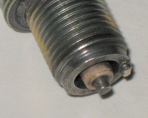
There were real coil and spark plug testers equipment in old-time repair shops. These testers were sometimes a combination coil & spark plug tester; but both types were often slangly referred-to as 'bomb testers' (yes, really), & used a chamber that could be pressurized by shop air. The chamber had a tiny window in order to observe the spark. However, above the photo I describe spark jumping on the modified spark plug, and this is adequate for your coil testing, combined with use of an ohmmeter first. Be sure the spark plug is grounded to the cylinder, use a bungee or? The spark plug cap must be securely on the spark plug. Observe in a darkened area while engine is being cranked. A good blue spark is required.
If one cylinder is acting up, and the other seems OK or nearly so, SWAP the ignition secondary winding leads; that is, swap the tower leads (even on 12 volt twin tower coils), and if the other cylinder now acts up, replace the coil.
Use of spark plug adapters that are sold for ignition testing, including for coil testing, such as the Colortune, are absolutely not recommended by me (and OAK). They may damage your head threads. They are NOT useful for testing the ignition system, no matter the manufacturer's claims!
The first updated twin tower coil was black bodied.
Coil Substitutions, in brief: An Oilhead coil could be used. The Oilhead coil was 12-13-1-341-978. The plug housing primary side is 61-13-1-459-515; the connector for the housing is 61-13-1-459-516. The Secondary side (ignition cable to the coil) is 12-12-1-289-837. Connector for the coil is 12-12-1-705-656 ...needed because the cable can't be screwed into the plug. Add a rubber cap at the coil. Bosch does have a part 0 356 250 033-000 plug & it can have the cable screwed-in. You could use two each 6 volt Bosch coils, which can used on electronic module Airhead motorcycles from 1981. To be really correct, you need the proper coils ...but, just substituting the Oilhead or 6V Bosch coils will work OK, if not 100% optimally. The 6V Bosch coils with the lightning bolt on the side has the correct electrical characteristics. The part number for the coils through 1980 is 12-13-1-244-142. If substituting for a single two-tower coil, mount one coil where the original twin-output coil was. Use that coil for the left spark plug. Mount the other coil towards the rear, under the relay bracketry, and use it for the right spark plug. Interconnect terminals 15 & 1 between the two coils. The remaining terminal 15 goes to the original green wire; the remaining terminal 1 goes to the remaining black wire. It is a good idea for the coils to be solidly mounted such that a good electrical contact is made to the metal body. These Lightning Bolt coils are generally very reliable. Some models had a reddish-colored dual tower coil from around 1991, and they seem bulletproof. The red coil has a primary of 0.50 ohm, often said to be 0.70 ohms. Do not use early electronic ignition modules with these coils .....see information well above & maybe further on. Do not use these coils with points ignition, unless you have a high power points amplifier/booster; and, in such service they draw more power from the battery. The original gray two-tower 12 volt coil was 1.15 to 1.35 ohms. It is possible that some of the numbers I used in this article are not in the BMW North America ordering system, but they exist ....and your BMW dealer can get them. COILS ...PART 3: There are several possible failure modes, but the most common causes are two. One is that the case plastic (or tar inside of metal case coils) and the copper and iron core parts inside do not expand and contract with heat changes at the same rate. That stresses the extremely thin wires of thousands of turns, used on the secondary winding. Being of copper, those wires also expand and contract with temperature. The wire needs a good compromise in its own characteristics too. The other common cause is lifting the spark plug cap with the ignition power on ....that causes an extremely high voltage to be developed in the coil, until it either jumps around inside, or is otherwise grounded. The jumping around can be between turns, and the result can be an insulation break-down. One or more places in the secondary windings can break, and this can keep happening, over time. These wire breaks cause high voltage sparks jumping, which further degrade performance. The main degradation is often short circuits between nearby windings, but sometimes the windings are far separated, and that always greatly reduces spark energy. That acts, and is, like a single or modest multiple turns shorted loop surrounding the entire coil. Thus, a double whammy ...the open due to the break, and the shorted turn, acting as a shorted secondary winding in itself. That shorted turn absorbs energy the coil was designed to use to produce the high voltage for igniting the fuel-air mixture inside the cylinder head. There is a particularly well-known instance, where, on some models, BMW installed a single coil with twin towers, the coil case was easily identified because it was all-plastic & gray in color. It would test fine when new, but was poorly designed and poorly manufactured. It is tricky to encase the coil electric parts, control the cooling, etc., and the plastic type formulation is also critical. The coil(s) are charged from the battery when the POINTS are CLOSED. The points are closed TWICE, for each points cam rotation. The points are also opened twice, each of which opening causes the coil to discharge. The period of time the points are closed, with reference to a single 360 degree rotation, is called the dwell. The dwell is expressed as degrees compared to a full rotation, and dwell must be large enough for the coil to fully charge for every ignition event to take place using a full charge. As RPM increases, it is obvious that the time for charging decreases. That can lower the coil voltage output once the RPM is high enough. Coils have numerous electrical characteristics, but one important consideration is that the coil output must always be high enough for a good coil output at any RPM that the engine is likely to be able to attain, and the ignition must still work well if the battery is not fully-charged, or the battery voltage is decreased by age or cold temperature. Allowance must be made for all factors, including stiff oil and reduced clearances on a cold engine ...etc. Note: Points closure is, in effect, duplicated by the ignition control module, in the 1981+ electronics ignition modules. The dwell angle is different on those models, but all the theory is the same. When the module turns off, the coil discharges. The module is driven by a magnetically sensitive transistor, opposite which is a butterfly metal piece, so there is two poles of the butterfly rotating past the transistor. When the points close (or module turns on), the coil, having been discharged by the previous spark event, now has ~12 volts applied. There are complex equations to calculate the coil current at any point of time during the charging period of time, as it is a curved exponential function. In points models there is a capacitor, called a condenser, which most think is used only to suppress points erosion from sparking, but it has a considerable complex effect on high voltage generation. I will NOT get into any of this, being way beyond what is needed in this posting. Simplified for our example here, let us suppose the coil primary winding is ~3 ohms, and the battery is presenting 12.5 volts to the coil, and the points are closed. Ohms law says that 4.17 amperes is flowing, and the power in the coil is 52 watts. The actual averaged heating is less, because the points do not stay closed, and in fact are open for two periods during that cam's rotation (2 cam lobes). One can calculate by using the dwell angle and some fancy math; but, the results still are that a considerable amount of heat is developed in the coil windings, and this is besides engine heat rising up to the coil. The coil can get rather hot inside. Heating (and cooling cycling) is not good for the coil. Thus, the coil designer wants low heating, low heat-cold expansion effects, sufficient energy and voltage output, and good heat dissipation. Many many decades of ignition coil design experience can still, as we've seen, result in problems from actual manufacturing practices.
If the points cam is too sharply pointy, the points may not operate correctly by failure to 'follow' the cam shape...they can bounce, or otherwise not stay closed long enough, and may open too much. Compromises must be made for shape....but are rather easily accommodated for modest RPM engines with small numbers of cylinders. But, the dwell must not be excessive, or the heat generated in the coil will be excessive. This happened on the Authorities (Police) bikes in the /5 era. The basics were the same, but for radio interference reasons, the coils had metal shields around them. That shield enabled the coils to RETAIN more heat than in the non-authorities models. Coils began to fail. The system has always been rather over-designed for Airheads, so BMW elected to change the points cam to one with less DWELL angle. This worked well, so BMW elected to use the same points cam for all the bikes in the second (of several) points cams era. There are other considerations, such as coil output must be considered, and how fast it appears from zero to peak value before the spark occurs at the spark plug. These considerations will generally keep the designer of the coil from lowering the primary current too much. Dwell angle has varied further as time went on and ignition output needs changed, particularly with the 1981+ models that required a more powerful spark to reliably ignite lean mixtures used to help reduce emissions (smog). BMW went to a lower ohm primary that increased input to the coil, to further improve the high voltage output characteristics. So, there are various compromises in coil design. The very last of the modules and coils were probably the very best that BMW and Bosch could do, without going to a capacitive discharge system with its complications. Certainly, the last module and coil were more than adequate for the stock engine; and, for that matter, certainly plenty good enough for a quite hopped-up engine too. There are 'meters' with Dwell function measurements available, usually these are Automotive type Multimeters. They need not be expensive. Most do not read properly for two cylinder engines, but one simply applies a single multiplying factor, and uses the 4 cylinder position of the switch. Some folks set points gap by means of a Dwell meter. This can be quite accurate, but is not needed with our Airheads. IMO, doing so can even create problems if the points are too narrow from adjustment by dwell angle, and poorly made points can exacerbate the situation. I can argue these points. The specifics about the ATU's, by BMW and Bosch model number are, of course, shown in this website, for the curious. More about ignition theory itself, and how the ever-so-simple-appearing Kettering ignition REALLY works, is also on site. If you are not completely brain-dead from reading all the previous; ......here is more information; ....before I get into things in depth! 1. Suppressor (resistor) spark plug caps were metal sheathed from 1970-1976, 1000 (1K) or 1200 ohms nominally, depending on which piece of literature you are looking at. The tolerance is officially +-20%; so if they measure 800 to 1500 ohms, that's OK. From 1977 all caps were 'nominal' 5000 ohms. ALL points bikes can use 1000 or 5000 ohm caps. NGK caps, with the added rubber protector covers that they usually come, are preferable to the metal-covered BMW/Beru types strictly for long term protection against spark jumping ...but the BMW/BERU types are OK ....if you clean the insides now and then ...and they do look nice. The stock electronic ignition bikes (1981+) MUST have 5000 ohm, often just called 5K caps. If the actual value was much lower than 2500, the ignition can be long-term damaged. The 5000 ohms is 'nominal' in specification. NGK numbers for 1000 ohm caps are LB010F; for 5000 ohm are LB05F. They make 10,000 ohm caps too (LB10....), so be sure to actually measure them, you might be confused by the part numbers for 1K and 10K and you definitely want good resistors. BMW uses spark plugs with stud threaded tops, needing matching caps. Some Airhead motorcycles had metal caps molded to the cable,& most were 5000 ohms. There is an article on this website with extensive information on spark plugs and all the NGK caps information, etc.:
https://bmwmotorcycletech.info/sparkplugs.htm 2. Where so marked, coil terminal 15 & 1 and/or + and -, all have meaning. With two coils models one coil is jumpered from terminal 1 on one coil to terminal 15 on the other coil. The remaining terminal 15 goes to the ignition switch; the remaining terminal 1 goes to the points (and tachometer if electronic type) or ignition module. This maintains proper high voltage polarity at the spark plugs, as well as having a complex effect from reverse voltage in the system, that need not be explained here. NOTE: There have been instances of misfiring on bikes as shipped from the factory with miss-wired coils. This has been seen only on the R45 & R65 (AFAIK). Check your motorcycle. Example, a 1979 R65: The rear coil should have a green/blue wire (12 volt + power) going to terminal 15. On that same rear coil there is a black/yellow wire going to terminal 1, which connects to the front coil terminal 15. The front coil should have two black wires going to terminal 1; one is to the points, the other to the tachometer. 3. QUICK TESTING of coils & ignition caps:
More on Failure modes, etc. A simplified version of how coils, points, electronics modules, etc., actually work.
1981 & later Airheads have electronic ignition. The ignition caps absolutely must be nominally 5000 ohms each. Do not use resistor spark plugs!!! Do not eliminate the 5000 ohm cap resistors by using a zero or l000 ohm cap.
b. A somewhat better test (although none of the above, nor this one, nor the following tests, will show up some types of shorts in the coils), is to first unplug the spark plug wires from the coil towers. Measure one of the spark plug caps with the wire attached to it, from the contact inside the spark plug cap to the other end of the wire, the folded metal end. Then measure the other one. 4K to 8K is acceptable for the electronic ignition models; and about 800 ohms to 8K for the points models. 1K rated caps are the best for all points models performance, although those were only installed on the early motorcycles, as has been noted. You can also measure a coil tower to any side terminal (single tower coils only); then measure the other coil similarly. Be sure the metal at the bottom inside of the tower is clean and shiny. About 4K to 5.5K is OK for either coil. For the single twin tower coil, measure between the two towers. About 7.5K to 9K; and infinity between a tower and primary terminal (same for towers to ground).
The spark plug wires brass pressure contacts should fit tightly into the coil towers & both wire contact and the tower inside metal need to be clean and shiny ....if not, fix these things. I recommend, once things are shiny and clean, that a faint smear of silicone dielectric grease be put on the folded contact that goes into the coil. Others disagree; industry practice is to use the grease only on the inside of the rubber boot. I believe industry practice is wrong, because you, correct? ...will first see to it that your clean/shiny wire folded brass fitting ends fit tightly! ...into clean/shiny towers. If so, the grease will eliminate corrosion .....for MANY years, if not decades. Insert the wire, which will need some decent force (I use pliers) to seat it fully; it will almost snap into place with enough force.
c. Measuring the PRIMARY winding side of any coil is more difficult, as for an accurate reading you must short the ohmmeter leads together rather well, then subtract that reading from the primary reading, which also must be a good connection for the meter leads, which must not be moved in their meter sockets during the testing, lest you have irregular readings. The reading should be quite low resistance, which is always more difficult to measure properly. Primaries very rarely open or short. You can simply check for a low resistance. I won't even list the exact values you might get, but for the twin-tower coil it will be around a half an ohm to around one ohm; & ~ 1-1.5 ohms for the two separate 6 volt coil models. Obviously the values must not be a direct short, nor open.
d. The best test is probably by substitution with a known good coil, to see if whatever the ignition problem was, it is now OK (or, not).
e. The second best test (possible first best?), & this test is quite good, is that you first ohmmeter the coil as previously described, and then test the coil both cold & hot with a modified spark plug. My method of doing this was described earlier in this article.
f. NERDY:
BMW published a spark gap test for the 6 volt coils prior to introducing, in 1981, the electronics models. While I think the test is relatively decent for the electronics models, I have not seen a published test from BMW, perhaps due to the possible damage to the system if the test is not done correctly. The old test is for a minimum 8 mm spark at 300 sparks per minute at 3 volts to the coil; with the spark lengthening to 13.5 mm minimum, at an unspecified primary voltage, at 3600 sparks per minute. BMW's specification was the same for all the different ATU dwell versions including the early 78� & later 120� with the 1979-1980 points-in-canister model. You need a special setup to do those tests, which are stressful on the coil, and IMO, more stress than what you should do. You will notice that the test is done at 3 volts of battery power & uses 8 mm AND 13.5 mm test gaps. 13.5 mm is a fairly severe test. You may notice that BMW's figures on the lengthening are reversed. If you want to make up testing jigs & do these tests, fine by me. I recommend you don't. Additional problems with the BMW specs were that the gap test did not, in my literature, specify the two parts needed for the gap, & pointy gaps need less voltage. BMW probably (?) meant that the tests were to be done with one of their 'tools', & it had a free-air gap, etc. If using a 12 volt coil (BMW only used 12 volt coils of the type with two towers), then apply 6 volts, and use only one spark plug, the shell to one tower, the spark plug stud to the other coil tower. Actually BMW was wrong about lengthening with RPM, so, this entire paragraph is for reference purposes only, in case you see the BMW information someplace...IT IS ALL WRONG!
4. BMW Airhead points bikes have two cam lobes on the Automatic Timing Unit (ATU). On the models up through the 1978 model year, the points & timing unit are mounted at the nose of the camshaft & not in a canister. The forward part of the camshaft, that nose area, of non-canister models, can be found bent at times. You will not see that with your eyes. There is a way to fix it, with a small brass hammer, but that is not the main point of what I want to emphasize here. The bent part may be only a fraction of a thousandth of an inch to a few thousandths. As the ATU rotates, the points will not have the exact same gap nor timing point ...for both ATU timing lobes. This will result in a dual-image when using a strobe lamp on the flywheel. The result is vibration, often at one or more narrow ranges of RPM. This type of problem is often wrongly interpreted as carburetors being out of perfect synchronization, or, the engine is mechanically not balanced, or has some other mechanical problem
The Dyna dual-pickup electronic ignition will eliminate much/most double-timing, and there are other ignitions available for the camshaft nose, and there are crankshaft mounted ignitions available. The camshaft tip is, as noted, fixable. Another cause for this sort of timing change is advance unit wear &/or irregularity in the grinding of the cam lobes. BMW at one time actually recommended 'stoning' those lobes to equality. Don't bother!
A quite poor ATU and/or cam tip needs fixing, somehow. An expensive way, is to purchase a crankshaft triggered ignition. These can provide very good ignition, and eliminate ignition problems from a bent tip and also worn timing chest items...but do not fix the retardation of the valves from worn timing chest items. A worn timing chain, chain guides, & wear on one or both timing sprockets, will also cause double images on the stock standard ignitions. Quite noisy chains at on and off idle rpm with the throttle are a giveaway, but the chain need not be noisy. The cam tip "tapping with a brass hammer fix" must be done carefully, not knocking off the threaded cam tip. Use of a dial indicator on the smooth side area surface of the cam tip will tell the story ....and if you have fixed the problem ...or made it worse. Do not try the brass hammer fix unless you know what you are doing, have a dial indicator, & know how to use it.
5. The electronic ignition came in 1981 and the dwell angle was 104�. For the points models, BMW has used three different dwell angles: 78�, 110�, and 120� (of crankshaft rotation), with 120� being used in the 1979-1980 canister points models. Much more information is located in the following:
https://bmwmotorcycletech.info/ignitionsingleplug.htm.
ATU parts interchange physically for all pre-1979, so you might have almost any year/version of ATU or ATU parts in your motorcycle. I've posted the various Bosch numbers printed on the outer metal, versus the timing and dwell. The springs have also varied.
Here's the .gif of most of that information:
https://bmwmotorcycletech.info/Atu.gif
What is not shown is the full Bosch number; nor is the rpm for beginning the advance (which can be slightly below 800 rpm on the early /5, so if the /5 is idled above that, readings can be strange, if you were not informed. Now you are.
6. The rubber seal strip located in the PRE-1979 timing chest, in a groove surrounding the points cavity, has two part numbers in the parts books. These come in lengths you cut to fit. Install it after cleaning them with acetone or MEK, & clean the cavity for it quite well too. Put small droplets of cyano-acrylic glue (CrazyGlue, etc.) in the cavity groove, before installing. Push a few times into position if need-be, cut with an Xacto knife to fit the ends rather tightly; & let sit overnight. CLEAN with acetone or MEK again & smear a faint amount of silicone dielectric grease on the surface, before replacing the outer cover. Be careful to engage the outer aluminum cover into the points cavity rubber grommet slot.
11-14-1-265-394 is supposedly 3.2 mm, used until 1974.
11-14-1-262-644 is supposedly 4.2 mm, used after 1974.
If you were to order either, you probably will get just -394 size. Maybe. Also, some fiche may show a substitute for either number, 11-14-2-300-295, which is not a good number.
I have plenty of various O-ring materials around, you may not....and...Tom Cutter said you can use a Classic K bike oil filter cover O-ring, which is 11-13-1-460-425, even a used one (I do suggest you clean the groove and O-ring material quite thoroughly, before you try to glue it to the engine)!
7. You may occasionally need to know the spacing between markings on the flywheel (or clutch carrier). You may need to know the distance per degree on the circumference. The diameter for the larger engines are all the same and there is 2 mm between each degree. For the R45/R65, the diameter is smaller, so it is 1.5 mm between each degree.
Accel m/c products; 10601 Memphis Ave #12; Cleveland, OH 44144; (216) 688-8303; part of Mr. Gasket group.
www.mrgasket.com
Accel points amplifier, wiring schematic: see page 38 here:
http://www.rubberchickenracinggarage.com/Downloads/TomCutterDualPlugIgnition.pdf
The sketch is for dual plugging coils, but OK for single plug coils.
Alpha (Emerald Island) ignition (canister):
Rick, at Motorrad Elektrik, told me that the brown Dyna coil (1.5 ohm primary) works fine with the Alpha ignition system. He told me the latest Alpha version also works OK with the blue 0.7 ohm coil. I am speaking here of one single coil, dual output towers, not dual-plugged.
I don't know, yet, about long term use/reliability using the Alpha2 ignition system with the stock last version BMW 0.5 ohm coil, but my limited testing showed it being OK on my own 1995 R100RT, which has the Alpha ignition. See next paragraph.
Ted Porter (Beemershop.com) who stocks the Emerald Island electronic ignition (Rick, above, calls his, which is the identical item from Emerald Island, the Alpha 2), has a lot of experience with this ignition, & he reports NO problems with any of the stock coils including 1.5 ohm coils (two in series, 1970-1980 coils), & the later low ohm stock coils, & the Dyna DC9-1 0.7 ohm coils in series, and also the 1.5 ohm DC2-1 single coil.
NOTE: The EI (Alpha, etc.) electronic ignition uses its own version of the module, and uses electronic advance, not a mechanical ATU. There are, to my understanding, two standard sold versions, one for single plug, one for dual plugging....and they have been changed/updated/modified/whatever, over time. I am not overly happy that the specified number of degrees of advance (well, the spread) is not accurate, by 2 or 3 or so degrees. Maybe that will get fixed.
Dyna:
Technical information on most models is available at:
http://www.dynaonline.com/
You may find some of the information confusing ...so I will give you clarifying information here.
For the 70-80 points Airheads, Dyna sells an Ignition Booster ....and it can also be used for a dual-spark-plug modified Airhead, with correct selection of the two primary coil resistances, to keep within the booster current limitations. Pay attention to the coil(s) resistance for non-dual-plugged installations too, of course!
Here is the original dyna installation instructions:
DYNA IGNITION BOOSTER, INSTALLATION INSTRUCTIONS
Part No. DBR-1 for engines with single breaker points
The DYNA Ignition Booster was designed for use with stock or aftermarket coils or combinations of coils that have at least
THREE OHMS primary resistance.
1) Fasten the clamp to the electronic module using the 4-40 x 5/16 screws and locknuts provided. The clamp and nuts go on the inside of the housing.
2) Attach the module to the frame in the location selected. Cut off excess clamp material.
3) Attach the ground lug (black wire) to a clean ground point. The engine case is recommended, however, a good frame connection can be used if necessary.
4) File the points regardless of their condition, even if new. Snowbum recommends just a careful cleaning and VERY lightly filing, using 360 OR FINER grit sandpaper, VERY carefully...one slight pull-through, then reverse the sandpaper and do the same to the other point. Leave the condenser connected.
5) Disconnect the points wire from the ignition coil, and connect the blue wire from the booster in it's place.
6) Connect the white wire from the booster to the breaker points wire removed in the previous step.
7) Connect the red wire from the booster to the coil terminal that has + 12 volts applied to it when the ignition switch is turned on.
Dyna dual-separate-pickups electronics ignition allows separate timing for the two cylinders, which, in some instances, provides a smoother engine.
Many years ago, the original Dyna D35-2 system was not a wasted-spark system. They used DC1-1 green 3 ohm coils on the dual-plugged conversions & the sensor plate had three wires. Each cylinder could be set separately with a timing light. For a dual-plugged engine, since this was not a wasted spark setup, each coil fed one cylinder; that is, each coil fed the top and bottom spark plug on one particular cylinder). Dyna has not offered this D35-2 in many years. Now, what is available is the D35-1, wasted-spark model.
The D35-1 has two wires at the sensor plate; usually installed with 1.5 ohm Dyna coils ...which are brown or orangey looking, & are series connected. Timing is set with an ohmmeter or test light, as you rotate the engine by hand, so watch the magnet location, to know what side sensor you are adjusting. Yes, you could use a dual-plugging setup.
Watch out for bad Dyna sensor insulation; that is, broken or corroded wires at the sensor plate where they exit the epoxy, & for coils shorting a primary to ground when hot.
Use NGK 1000 ohm spark plug caps.
Dyna sells many different coils. Do not use the Green dual-tower ""6 volt in some literature"" coil with the Bosch electronic ignitions that came on the BMW Airheads from 1981. These Dyna coils are 3 ohms, and would be marginal in that application.
The popular Dyna III model D35-1 was for the 70-78 Bosch coils; or, Dyna coils.
The wiring for the Dyna box:
White, left cylinder.
Red, right cylinder.
Black is ground.
The other red goes to +12 at ignition switch & to the left coil (+). The coils are interconnected by a jumper, same as on original BMW, same numbers at coil primaries, if using those coils. The right coil (-) is the one with the brown wire from the Dyna box. Unconfirmed: Dyna III uses UGS3040T Hall devices.
DYNA III, type -1 and type -2 Electronic Ignition Trouble-shooting:
If only one cylinder is working on a -1 Dyna III it probably is a bad sensor. This can be corrosion, so remove the assembly and inspect it; it can be the sensor itself, bad wire, etc. If both cylinders are NW, it is most likely a bad electronic module, bad coil, or in the wiring.
MODULE / COIL TEST:
Disconnect the sensor wires and touch the module end of the input wires to ground. Do not touch the 12 volt (red) sensor wire to ground. You should get a spark at the appropriate spark plugs each time the inputs are grounded. If not, it indicates a bad electronic module, a bad coil, or a problem somewhere in the wiring not associated with the sensor plate. Check the Dyna website to confirm my testing methods.
Dyna coils are color identified, although you could use an ohmmeter for confirmation:
DC9-1 0.7 ohms;
DC2-1 1.5 ohms.
Boyer-Bransden (aka "Boyer"):
The old black box Boyer, the Mk3, can be used with or without resistor spark plug caps.
The Microdigital (red box) is sensitive to RF interference, so 5000 ohm spark plug caps are required. The unit won't be injured if you don't use these, but the microprocessor could ...or will ...go crazy and upset the timing.
URL for troubleshooting the Boyer MK 3:
http://www.oldbritts.com/boyer_testing.html. That site has a schematic diagram of some innards, operation, wiring, & spark curves.
http://www.boyerbransden.com/faultfinding.html Boyer's own troubleshooting guide.
The early Boyer ignitions have been known to cause rough running problems, & the bike being hard to start. This is usually from low battery voltage, typically a voltage under 10 or so, and/or SLOW cranking speeds, both of which are disliked by the old Boyer. The early Boyer models also have an ignition curve that does not match the Airhead engine requirements. In particular, the early Boyer had an ignition curve that was slow rising & kept rising, there was no practical rising limit ....the ignition would continue to advance with increasing RPM. Many are in use, however, on Airheads, with 'no problems noticed'.
I have the schematic diagram of the innards of the old Boyer units, with all parts identified, numbers, etc, & I also have the timing advance curve on the old (& the later, below) Boyer units, & I have it on other ignitions, such as the Lucas "Rita". For the nerdy, or whomever really needs this sort of information, they can contact me.
Some Boyer-Brandsden's can have a peculiar problem, being not easy to shut off the engine with the ignition or kill switch. A cure may be available by disconnecting the red fused wire that goes from the Boyer to the battery & the left (+15) coil terminal. Tape it & do not use it. Connect both green wires to that coil terminal.
The Boyer-Bransden ignition has been updated. The Boyer was always an ignition to consider when the tip of the pre-1979 camshaft was broken off, although that cam nose is usually repairable. Now, with the new Boyer model with the updated ignition curve (also available in a modified version for dual-plugging installations) (and supposedly now works OK with a slightly weak battery, low voltage that is, during starting), there is less reason to not recommend it.
www.rockypointcycle.com
Below is the Boyer-Bransden Microdigital Electronic Ignition advance curve, courtesy of www.Boyerbransden.com and obtained from Stan Smith when he owned rockypointcycle.
The ignition timing curve shows an ignition advance, a sudden rise in timing at 500 rpm and then a quick drop from ~500 to ~800 RPM, then a moderate rise starting about 1100 RPM. This can cause some noticeable irregularities in response if the engine is idled too slow, even slight strangeness on starting. This model does have a limit on advancing the spark, at about 4000 rpm. As noted well above, the older Boyer did not have a limit.On the chart curve, the ignition advance curve is in crankshaft degrees, the most common descriptive method. The camshaft degrees method, when used, is often called "distributor" timing or distributor degrees.
Emerald Island (Jeff Lee) canister ignition kit, as sold by Motorrad Elektrik (as Alpha 2) and Ted Porter's Beemshop: I have been informed by Rick Jones of Motorrad Elektrik that the module on these is OK for driving stock, etc., coils, such as the latest BMW Airhead coils, or a Dyna blue 0.7 ohm primary. The Dyna brown coil of 1.5 ohms is also supposed to work well, although I personally have some reservations about that one, but have not yet done a full set of tests ...but am running it in my own 1995 R100RT. The canister ignition unit and module is sold in other countries under other names, one of which is Red Centre.
Ted Porter (Beemershop) who is stocking the Emerald Island electronic ignition (Rick, above, calls his, which is the identical item from Emerald Island, the Alpha 2), also has a lot of experience with this ignition. He reports no problems with any of the stock coils, including 1.5 ohm coils (two in series, 1970-1980 coils), Dyna DC9-1 0.7 ohm in series, & also the 1.5 ohm DC2-1 single coil. Reportedly the 0.5 ohm BMW coils work fine with it too. I briefly tested that, seems OK. No other reports so far, except that the module advance curve is a few degrees shy of the specified amount.
Crankshaft mounted ignitions: NONE so far thoroughly tested by me. I am not convinced that one of them, under the Silent Hektik brand, is worth the price.
Oilheads and Classic K bikes:
Information on the module & Hall sensors in the article you are reading has similarities to the Oilheads & K bikes.
Getting deeper into the Airhead (much applies to the Classic K bikes) electronic ignition:
How to Test the Airhead Ignition Module, a more thorough test series. The more technical aspects, etc.
Some information & photos below, were from Thunderchild's website, for whom I give credit. I have done considerable editing & modification to Thunderchild's information, & added my own comments ...mine and his are not clearly identified. The ignition system of a 1981+ BMW motorcycle equipped with electronic ignition consists of three major parts: the coil (or coils), the ignition trigger & automatic advance unit (in a canister) & the ignition control unit called the ignition amplifier or module. The coil(s) are usually easy to test, but verifying whether the trigger or the control unit has failed can be a bit more tricky. A rare failure is a coil that fails to work properly when it gets hot. A not rare failure is the early single coil models, in which the coil is gray-bodied. Those tend to crack and fail, often visibly, most often failing when exposed to high humidity or moisture. A large amount of information on testing various parts is in the earlier sections of this very long article. In this section, I get deeper into technical discussion & testing, with a few repeated things to remind you of SOME earlier remarks. Following this gray-colored area are more comments, more testing information, etc. Referring to the wiring diagram, three wires go from the ignition trigger (in the canister) control unit to the ignition control unit (module). The canister Hall device (trigger unit ) obtains power from ICU Module pin 5; the trigger signal is developed in the Hall device and sent to the ICU module pins 3 and 6. Each time the trigger wire, that is the center terminal of the three-terminal cable of the canister, goes to ground, a spark should be generated from the high voltage produced by the coil(s). The above sketch has the actual order of pin numbers. The schematic diagram to the right does not show these numbers in actual physical order. Testing the control unit (module) should be as simple as powering the unit up & repeatedly grounding and un-grounding the trigger wire. This does not test the module for all conditions of temperature changes. The procedure is as follows (be sure to read all of this!): 1) Unplug the connector that connects the harness from the canister to the harness from the control unit. Be careful as there is a small diameter round 'bale' wire used as a clip to hold the connectors together, that must be removed first. For access to this plug, simply disconnect the battery first (to protect the diode board from inadvertently being shorting by cover removal), then remove the metal outer cover over the front of the engine. The plug is roughly centrally located. 3) With the connectors still separated, stick a pin or fine wire into the center connector of the 3 conductor white connector coming from engine harness (not from the canister harness side). 4) Re-connect the battery. With the ignition switched on, & the bars KILL switch ON, momentarily ground the pin/wire you just added coming from the center connector. Each time you do this you should get a spark at the spark plug. This will indicate that the control unit module under the tank is operational. 5) An even simpler method that can be tried first, but is not 100% foolproof is to turn on the ignition switch & have the kill switch in the middle ON position. Turn the kill switch OFF, then back ON, then OFF. Every time you turn it OFF from the ON position, you should get a spark. This tests, as does the previous test, only the coils and some of the module, not the Hall element in the canister, nor the part of the module that processes the canister signal. This test gives somewhat different indications if you have the very last of the modules, with the torquoise printing, from Telefunken. It is not unheard of for the module ...or Hall device in the canister ....or any other piece of electronics for that matter, to operate perfectly when cold & fail when warm/hot. Corresponding Ignition Control Unit numbers, compared to Bosch motorcycle standard wiring numbers: 1 1 coil Information on the pin-outs, etc., are in SI's as follows: In the wiring diagram below, the Ignition Control Unit Module pin numbers are not in the actual order they are seen on the part (see sketch on the left side for the correct order, which reads right to left, in orderly progression)...that means that on the part itself, with the unit laying flat in front of you, metal on bottom, pins towards you, the pins are numbered from right to left, first pin on right is pin #1, last on left is pin #7. DO NOT! use an ohmmeter on the module pins. The sketch is copied from a full wiring diagram. Although not drawn as such in the diagram, the trigger wire (to pin 6 of the unit) is the center connector. The ignition control unit pin 6 has a brown wire; pin 3 has a blue wire, pin 5 has a green-yellow wire; pin 4 has a green-glue wire, pin 1 has a black wire, pin 2 has a heavier brown wire. The ignition trigger plug green/yellow (pin 5) may be violet; the blue may be violet/white; and the black may be violet/black. Inside the canister unit, the sensor has a red wire which connects to the violet or green/yellow; a green wire which connects to the violet/white or blue; and a black wire which connects to the violet/black or black wire .....in the plug. Testing the Ignition Trigger in the STOCK Canister, all by itself: Do not use ohmmeter functions of your test meter to test the Hall canister device, as it can damage the device. The three pin connector that connects the wires from the canister to the bike wiring, as noted above in the gray area, and elsewhere's in this article, has a thin wire bale clip around it that must be removed before you try to unplug this connector. Pry an end, or both, with a tiny tool, & then carefully remove that bale clip. Then unplug the connectors. Don't lose the bale wire. Don't spread it wider too far. Don't pull the connectors apart by gripping the wires. These connectors, over a very long period of time, can get brittle, so uncouple them carefully. Many have searched for a replacement for a damaged three pin connectors. I have not checked into this myself, but it may be that 90's Audi V6 cars (and others) have othem, so you can try a car salvage yard. Reportedly located in the engine area, left side, near firewall. If you need the connectors, I suggest brand new ones.
www.Euromotoelectrics.com has a brand-new replacement cable assembly parts with plugs, pins, etc. "BMW R Airhead 3 pin plug set for "Bean Can" Sensor - 12 11 1 244 088-1" Tom Cutter, one of the very helpful Guru's on the Airheads List and on Facebook, and who has decades of BMW repair expertise, probably stocks the plugs too. I suggest you contact him first ...it is always good to patronize those who help Airhead owners with constant free repair advice, etc. [email protected] The ignition canister contains a Hall Effect (magnetically sensitive) sensor; which is a special type of transistor. A rotating metal part, sort of a butterfly or figure eight in appearance, is in close proximity & provides the means to trigger that transistor. Rotation causes a voltage on the output to vary, thereby triggering the the ignition control unit module. The diagram showing how to wire to the connector for testing. "To can" means that end goes to the canister cable plug. The unit is powered from a 9 to 12 volt power supply (just use a 9V battery), & the output from the sensor (center pin) is pulled 'high' (that means positive) through a 10,000 ohm resistor. You read the results on the voltmeter, shown as a circle with V. As the shaft on the canister is rotated, voltage from the center output pin will fluctuate between a few millivolts and the + supply voltage. If this makes no sense to you, then it might be wise not to invite trouble. This test will not show up intermittent or heat related faults in the hall device; unless you do testing at various temperatures. An extremely rare problem is a module that will test OK using the wire grounding or the Kill switch methods; both are in the previous gray area information; and, this Hall Effect transistor test method with the battery and resistor and voltmeter also checks good. The answer is a bad module.
Overhauling/repairing Ignition canisters; who does this, and, sources for your parts, DIY: Here is a link to a source for the entire ignition plate with the Hall devices, ready to install. This may well be what you might want to do: https://www.motobins.co.uk/ Search the site for ignition "trigger assembly black box" or something like that. The part number is 07912 for the ignition plate with Hall device. Motobins also has entire canisters for sale. www.euromotoelectrics.com has repair kits ...the plate with Hall element and wire/plug, etc. ($$). BMW is also now selling repair kits ($$$$). Here are some sources and information for repairs, etc., on the electronics canisters: R-Bike Electronic Canisters, by Pete Serrino;
[email protected] That link may be NG, and you would have to try to find Pete. Troubleshooting Ignition Trigger, as posted to the BMW Airhead Boxer mailing LIST, on 19 April, 2001, by John W. Snider. See the LIST ARCHIVES. Ignition Trigger Repair Bulletin, by David A. Braun, July 1997, updated February 2004. This page still exists on the Internet, at least at my last check, on 07/29/2020. This is a worthwhile read. http://www.deathstar.org/~flash/ig_trig.html NOTE: Long ago I was accused by him of plagiarism. After some correspondence, he agreed that I had NOT, &, in fact, my information pre-dated his. I am listing the URL here, because it is useful; I do NOT hold a grudge, nor any ill-feelings. I only mention this incident because some things about this got published for a brief time, & published things tend to last forever on the Internet, whether or not someone sees any follow-ups. Read the article. It says some things a bit differently than I have, which can be helpful to some of you. Tom Cutter is overhauling the canisters. http://rubberchickenracinggarage.com/ You can also refer to the archives of the Airheads LIST and IBMWR. Sources for just the Hall elements in the USA seem to be disappearing. They are available from Chinese sources, limited feedback shows them working OK. Hall devices: Honeywell (MicroSwitch) part #2AV54. It may be that this was the original part. A Chinese source: I have seen these advertised, but have not yet tried them. Hall-Effect Vane Sensor BBHME56 (replacement for sensors 2AV54, 2AV16A, 2AV51A, 2AV56, 2AV63, and similar parts) http://bbautomacao.com/home_hall_effect_sensor_cyhme56.html The Honeywell device, in case you try to find its listing to obtain information on it on the Honeywell website, can be difficult to find. That is usually because its official name on that site is "Hall Effect Vane Position Sensor". You can TRY using this which may well reduce your search time:
https://sensing.honeywell.com/. You will still have to look around to find the correct page. Honeywell constantly plays with location addresses in its website. You don't need to go find it, unless very nerdy, because I have all the needed information, and more, right here in this article. Unconfirmed information is that the Hall units may be found in 1979-85 VW; 1978-1983
Audi; 1979-1982 Porsche; and that Bosch 1237011052 may be the number. I have thought about recommending that everyone obtain a replacement Hall device; before they stop making them. Below is what the Honeywell 2AV54 Hall sensor looks like. Red, power; black, ground; green, signal. Older units had the sensor plates screwed together; the rivets were hollow; later
plates were a push fit, solid rivets. Some replacement parts use softer rivets, which
are easier to remove. Just below is a schematic of the Hall Effect device. Note that the output is an NPN transistor with open collector. Here is a link to an article on diagnosis & repair of the Oilhead Hall Effect ignition sending unit, with some explanations & details that may help you understand the Airhead electronic ignition .....& how to work on them: Some folks who are overhauling or rebuilding canisters: Tom Cutter,
http://rubberchickenracinggarage.com/ [email protected] Tom's shop is located in Yardley, PA. Shop phone: (215) 321-7944 Dwight Small, 514 E. Grand Ave. #103; Laramie, WY 82070 970-214-2610 [email protected] Does overhauls?? R-Bike Electronic Canisters. Pete Serrino
[email protected] Link may not work, and you may have to try to find him. Canister Disassembly, DIY: Some screws may be quite tight. You need a proper-fitting screwdriver. Don't bugger-up things. Remove the pin that holds the coupling to the shaft ....at the end that goes into the camshaft. You will need a small diameter round drift. Be careful doing this, some are found to be tightly, some are not. If quite tight, you may want to do this with a press, or make up something so as to use your vise. Do NOT bugger things up. Support the shaft! You will find some shims and a washer. Remove the cap (Phillips type screws). That cap normally has a spongy material on the inside. It tends to deteriorate. That spongy material can make a mess inside the canister ...once it deteriorates it moves all about. Remove the sponge. Remove screws for the bearing plate; remove the plate; noting how the plate fits. Note the big snap ring; and, how it fits in a groove. Remove the C clip. Remove the three outside screws. Looking inside the canister, notice the 3 tabs that those 3 flat screws fit into. Mark a tab & can, so you replace them later in the same position ...(if you want to), but the tabs are not equally spaced, so this is not important. Now remove the screws. The flat screws hold the retainer which fits the snap ring only in one direction ....a keyhole in the retainer matches a protruding stud on the snap ring. Note that how the big snap ring fits, where its open end is. Remove the plastic rivet from the wire strain relief. Note that the plastic strain relief has a tit, you have to pry or pull it out; once out, the strain relief moves in the slot easily. The coupler has a spring thing wound around a groove. Pry an end loose; remove from coupler ....you now need to remove the pin which is now visible. You need to improvise something that will not injure anything, to remove that pin. Do that now. Use a soft hammer to move the shaft through & enable removing the contents, do this a bit at a time with the plastic wire strain relief ...back & forth. Remove slowly, don't use a lot of force, and write down what you see about about the many washers, etc., you find. BMW does not sell canister parts (the Hall device may now be an exception). Motobins in UK sells the springs for the advance weights. It will be clear to you to remove an E-clip & another snap ring, which hold the 'shield' in place. Note the pin, locating the advance & shield. Don't mess up that shield! Don't loose the small location pin either. This is expanded upon in the next paragraph. Regarding the Sensor (Hall transistor), if yours has failed: It is very important that the parts be very well cleaned, and if need be the shaft burnished (I polish with very fine paper)in the ATU area. You need to use some judgment & have some experience here. Sticky ATU problems show up as increasing idle speed USUALLY when the engine is quite hot; ....as the parts expand from heat. The weights are on a Teflon thing, don't oil the Teflon> unless you have an oil that is exceptionally slow in evaporation & probably contains Teflon; ....I usually use a very light viscosity Teflon grease in that area. When doing the final assembly of the canister, pay attention that the shaft continues to rotate freely, in particular as you tighten the side screws. Ken Lee had one that "dragged the edge of the rotor with the bottom of the sensor housing between sensor and magnet" (his words). He suggested cutting a small relief slot with a Dremel tool for clearance. When mounting the canister to the engine, install a new O-ring at the base. The sensors vary somewhat in how they look and/or are mounted. Pay attention to what you are doing. There is more than one style of plates/sensor items. The mounting plate may have a second plate affixed; then you can't drill one rivet & use screws and nuts. One rivet can be ground down from the top plate. The new sensor comes with the mounting rivets imbedded in the plastic housing. You won't likely find a way to flatten the blind rivet between the plates. You can remove those rivets, & use the holes for your own rivets. Make sure the sensor is flat & flush with the plate ...it is a bit tricky, clearance is tight for the rivet tool, although you can modify one. The canisters that have a lower plate & upper plate assembly with the blind area can be worked on with some thought. You could drill a couple of access holes for a riveting tool. The Classic K bikes use two of the same type of sensors, just not in a canister!Oilheads are similar. Below is a link to George Turski's photo-show on Flickr, on cleaning & lubricating a canister ignition. I caution you to pay attention to my comments here: The group of photos on how to clean and lubricate the ATU (by George Turski): Another do-it-yourself (DIY), cleaning and lubrication of the ATU: http://gunsmoke.com/motorcycling/r100gs/auto_advance/index.html If you are modifying the canister ignition timing limits stops in any way, see the next section. Modifying the Airhead stock canister for dual-plug conversions (& in some instances, for single plug): The majority of this section is pointed towards those who have, or intend-to, install a dual-plugging conversion. However, some few of you may, for various purposes (including increasing compression ratio), wish to do a modification to the ATU for single-plug engines. Note that while the canister ignition is generally what is being described here, the same sort of weights and springs method is used in the pre-1979 ignition ATU's, and generally applies. One Popular Point Of View, which I shall call PPOV-1 here, is you use an idle ignition timing at the OT mark on the flywheel (or, Clutch Carrier); or, a very slight advance from OT; & leave the canister advance unit stock. This was the method that Oak preferred (and I did too, long ago). You could bend the advance ears outward just shy of touching the canister case inside wall. That adds a small amount of maximum advance. I personally have done these things & also sometimes I just opened the canister and modified the weights/stops for additional advance. Neither is a must, IMO. It is a fair amount of work to take a canister apart to modify the weights & stops. I have never published the exact method & amounts of grinding, etc. Bending the advance ears is not difficult, & you need only remove the tiny oval side cover to do it; if careful, no need to disassemble the canister. Whether bending or modifying the advance unit or not, using OT timing at idle rpm as originally published by OAK, decades ago.... will result, during carburetor synchronization, that the CV carburetor butterflies are being closed a very tiny bit more than stock (reasons in my carburetor articles). This happens with any dual-plugging! Thus, there could be (not always is) a very slight stumble as you open the throttle from the idle position, ....usually, if ever noticeable, ...with gentle takeoffs from a stop. The cure, for complex reasons, is to increase the size of the idle jet ...a typical increase would be stock 45, change to 50 or 52 or 55. This effect could also be seen in using the S mark timing, PPOV-2, as in the next paragraph. Note also, that the effect has been seen, AFAIK, only with Bing CV carburetors. PPOV-2 ....is that the stock S mark advance mark should be used ...and, if so, the advance should have its total amount available shortened (restricted) a bit. The typical reason given is that dual-plugging does amount to an advance of timing, in itself. That is true. That is compensated for, in PPOV-1, by retarding the idle spark adjustment from the normal S ....to OT. For PPOV-2, an interesting article was posted by Pete Serrino. He recommended using one or more layers of common electronics shrink tubing over the advance weight stops. He did not specify the exact type of tubing, but said that one layer of tubing shortened the curve by 2� crankshaft. Snowbum notes here that 2� is NOT as much as the difference between S and OT, which varies by model & year, but is either 6� or 9�. Pete uses 2 layers for dual-plugged 336 camshaft bikes, & 3 or 4 layers for 1000 cc 308 camshaft bikes; & one layer less on 800 cc bikes. I do not think that restricting the advance range is absolutely necessary for this S timing method. I think it depends on many factors, including the compression ratio in use. Pete also said that drilling the weights with a 1/4" hole about 2/3 up from the pivot point & a 1/8" hole close to the first hole, will move the rpm up 500. I never published my own findings in that regard, as I did not want folks to willy-nilly do it, without real solid reasons. Rather, I have generally preferred slightly stronger springs to slow the advance (increase the rpm at which maximum advance occurs); but, like Pete, I never found many springs that did it, although some Porsche ignition springs were quite good enough. I have NO problem if someone wants to modify the weights....and is careful. Remember, an advance unit is costly to purchase. I have modified ATU weights on stock single plug engines to set the maximum advance a bit higher in rpm, usually to about 3500 RPM, which allows a bit more compression ratio even on Regular grade fuel ...or, allows a somewhat even higher CR with higher grades. You must decide on what you want to do, and why, and free advice (sometimes controversally) is available from experts on the Airheads List. I have purposely not expanded this section, as I did not want to cause more confusion.
NOTE: Ignition modules (except riveted models) must have a reasonably fresh thin coating of electronic heat sink paste between the module & the mounting plate. Failure to clean & re-apply such paste every 2 years or so will cause the module to overheat, interrupting the ignition, & with enough such overheating cycles, eventually the module fails permanently.
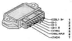
2 31 earth ground.
3 - Ignition, - trig
4 15 Ignition, light sw.
5 + Ignition trigger (+)
6 0 Ignition trigger (0)
7 tachometer output if used.
12-007-83 (2075) of May 1983. 12-006-82 (2061). 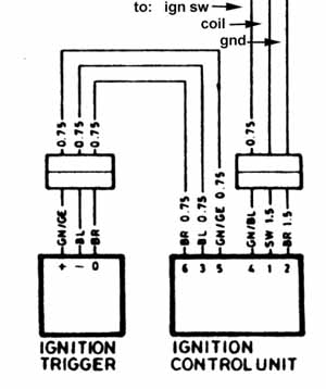
Further information on the three pin connector (male prongs) is in the next sketch in this article, at bottom right.
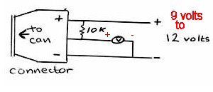
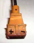
Note differences in the locating parts.
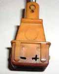
In this view of the MALE prongs of the connector, cable black wire to left, green wire in middle, red wire to right.
There may be others overhauling canisters.
What the heck is a Hall device? For a full and complete answer: https://en.wikipedia.org/wiki/Hall_effect
Reported other source: Siemens HKZ101 ....available from
www.Jaycar.com in Australia as ZD-1900.
I suggest you do some diligent searching & compare prices, and compare quality if you can ..... from these and other various sources for the various parts.
https://www.aliexpress.com/wholesale?catId=0&initiative_id=SB_20180102070558&SearchText=HKZ101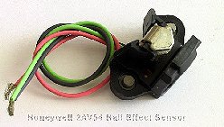
http://users.rcn.com/dehager/service/oilhead_hall_sensors.pdf It is possible to connect the Hall transistor to a transistor tester, and then lightly cool the device; and also, try lightly heating the device. You should get SMOOTH changing of characteristics from the temperature changes.
I suggest you make notes on what fits where, as you disassemble the canister.
Once the canister is basically disassembled, you need to remove the 'vane' without injuring it. The 'vane' is between two C rings. Remove the top C ring, and remove the pin (very small). Be careful. You will have to improvise something for this vane removal. You can now remove the other C ring, & the 2 flat head screws on the sensor bottom. The sensor is riveted and you have to drill (or?) that out ....replace with a pop-rivet or nut/screw. Use a Dremel or similar or?? to grind (or?) off the rivet. See note at end of this canister section, about the dualplate and blind rivet models. Cut the wires on the old & new sensors, so you can connect them & insulate them (shrink tubing). Be cautious about the re-riveting; keep things in proper shape. If the wires are long enough from the sensor, splicing can be done outside the canister. I prefer them connected inside; the wires kept short enough to avoid fouling on moving parts. The triggering magnet part of the sensor is retained by an E-clip & a snap-ring. The snap-ring does not hold the rotor in place, the pin does. The snap ring keeps the pin in place. The pin locates the magnet, with respect to the shaft. Don't lose that pin. Don't mess up here. Put the unit over a common socket of correct size, all on your workbench, hit the shaft with a soft hammer (plastic?).
1. Write down exact descriptions of where & how various washers, spacers, etc., are mounted/located.
2. Do not deform the advance springs by extending them at all beyond their normal stretch. You can see how much that is, by moving the advance weights to their stops. Do not remove them at all if you do not have to. If springs are already stretched, & weights would not be always fully returned at zero rpm, then replace the springs. Motobins, in U.K.
3. Don't lubricate too much. Use very light grease or a medium oil of long life quality.
4. Burnishing (metal polishing) may be needed. I use super-fine-grit silicon carbide paper & kerosene.
This link is provided by me here to give you an idea of what things look like, and is not how I personally would necessarily suggest you do a cleaning/lubrication/repair/etc.
https://www.flickr.com/photos/getproductions/sets/72157644751098893/
This is necessary, or is not necessary, depending on who you talk to; or, you may have your own ideas. Read this entire section through carefully. See the previous section(s) for comments about opening the canister.
Two complicating items to keep in mind:
1. The earliest /5 ATU's started the advancing at a quite low RPM. Some literature will say advance starts at 800 RPM. Since it is best for carburetion and system oiling, that the rpm be at 1025 RPM+-, this means that if you happen to have an early /5 ATU, you are already into the ignition advancing mode, if setting the carbs for off-throttle idle rpm over 800 rpm.
2. Partly due to 1., and partly due to spring wear on later models especially, there may be some slop in the weights before the springs start doing their job. Or, think about this as the weights being a bit free, springs or not, at engine off...and, maybe at engine at idle.
Think carefully about what happens in every mode.
I vastly prefer the later springs, so that advance does not begin until the RPM is a bit over idle rpm...this could mean 1300 or even 1500 rpm. I also prefer, especially on a performance motor, that maximum advance come rather soon, not later. This means that the early /5 advance, or a later one that someone has lightened the weights on, will be DONE advancing, at around 2000 to 2200 RPM. Don't do this unless you understand that you might get pinging on regular grade of gasoline even on a stock low compression bike.
If you want to experiment, or, want to chit-chat about your particular reasons/questions, you can contact me. It would be better to post to the Airheads List, where more folks besides you and me will get the information. [email protected]
I have an article on dual-plugging:
https://bmwmotorcycletech.info/dualplugging.htm
Addendum, miscl. notes, article wrap-up and final words, etc.:
Much that used to be here has been moved into the article. It is likely I will expand this section in the near future.
1. K bikes, and many other bikes (this does not apply to Airheads), do not have timing marks on flywheels, etc., for setting the ignition timing. In some instances, the ignition timing is set using a factory tool of some sort. Often, the ignition is specified to 'fire' at some specific distance of piston travel, almost always a certain distance from TDC. Occasionally in degrees. Article 72, formulas, includes the method for you to do the calculations, plus, a link to a website article that automatically does it for you. https://bmwmotorcycletech.info/formulas.htm
2. A rare, but super-annoying problem, because you likely will go bonkers before you find the answer, is a 1981 & later electronic ignition Airhead, that typically will idle OK, but won't raise rpm properly. This problem acts somewhat similarly to a hole in the carburetor diaphragms. The actual problem may be a poor ignition kill switch at the bars. Cleaning that switch may not fix the problem. Bypassing the switch will show whether or not the problem is that switch.
3.
� Copyright 2022, R. Fleischer
Return to Technical Articles LIST Page
Last check/edit: Thursday, May 30, 2024